
5-axis machining in aerospace manufacturing brings tool orientation, access, and process planning into one coordinated workflow. That matters when a part has compound surfaces, deep features, thin walls, or several faces that must remain related after machining. The value is not simply having two rotary axes. It is the ability to keep the cutter, workpiece, fixture, and inspection strategy aligned with the part's functional requirements.
This guide explains where the process is useful, how to plan it, which machine capabilities deserve verification, and how to control accuracy and surface quality. It focuses on aerospace structural parts machining, titanium alloy aerospace machining, and practical decisions that can be supported by a machine specification or a documented process review.
Table of Contents
- Why 5-axis machining in aerospace manufacturing fits complex parts
- How five-axis access changes aerospace part planning
- Aerospace structural parts machining
- Wing components
- Fuselage structural parts
- Control surfaces and brackets
- Satellite structural parts
- Titanium alloy aerospace machining
- Machine capability checks for aerospace work
- 5-axis machining accuracy
- Rotary-axis access and collision control
- Turn-mill operations for blade roots
- Process control from setup to inspection
- Datum strategy and fixturing
- Toolpath verification and compensation
- Surface quality and inspection records
- How to evaluate a five-axis aerospace machining partner
- Summary
- Request a process review
Why 5-axis machining in aerospace manufacturing fits complex parts
Aerospace components often combine large reference surfaces with pockets, webs, holes, blended radii, and angled interfaces. A process that reaches only one orientation at a time can still produce these features, but it may require more setups, more fixture interfaces, or more opportunities to transfer a datum incorrectly. Five-axis machining can maintain a planned relationship between the tool axis and the surface while the rotary axes move through the cut.
That capability should be treated as a process choice, not a guarantee of quality. The result still depends on the material, cutter, holder, workholding, machine condition, CAM strategy, postprocessor, probing plan, and inspection method. A responsible manufacturing review therefore asks which surfaces need simultaneous motion, which can be completed with indexed positioning, and which measurements will prove the result.
For complex curved surfaces, the most useful next step is a review of complex surface machining methods, especially when the design contains blended transitions or freeform geometry. The aerospace application remains the decision context here; the linked page covers the surface-machining angle in more depth.
How five-axis access changes aerospace part planning
The application decision starts with geometry and datums. A part may need five-axis motion because the cutter must approach a surface from changing directions, because the tool holder needs clearance, or because several surfaces must be completed without losing their spatial relationship. It does not follow that every feature needs continuous five-axis interpolation.
A sound plan separates three questions:
- Which features need simultaneous tool orientation, and which can use indexed positions?
- Which datums can be established and rechecked after clamping?
- Which machine, tool, and inspection limits are documented rather than assumed?
Aerospace structural parts machining
Aerospace structural parts machining commonly involves large envelopes, pockets, ribs, webs, and intersections between surfaces. The planning risk is often distortion or datum movement rather than a lack of nominal axis count. The process plan should identify thin or flexible regions, leave appropriate support during roughing, and define when semi-finishing and finishing measurements occur.
A five-axis machine can help keep the tool normal to selected surfaces and can reduce awkward tool-holder approaches. It does not remove the need to control cutting load, workholding stiffness, thermal behavior, and verification. For each critical feature, the manufacturing record should connect the drawing datum, fixture datum, probing routine, toolpath operation, and inspection result.
Wing components
Wing components may combine broad skins, ribs, spars, angled interfaces, and access-limited pockets. A useful process plan divides the work into stable roughing, controlled semi-finishing, and finishing operations. The objective is to preserve support while material is removed and to use tool orientation where it improves access or cutter engagement.
The plan should state which surfaces are primary datums, how the component is supported during each stage, and how the remaining stock is confirmed before finishing. Where several faces must remain aligned, indexed or simultaneous five-axis operations can be compared against a multi-setup alternative using actual fixture and inspection evidence.
Fuselage structural parts
Fuselage structural parts often place pockets, frames, attachment faces, and drilling features in different orientations. The practical benefit of five-axis access is the ability to reach more of those orientations while keeping a controlled coordinate relationship. The process still needs a clear datum scheme and a way to detect movement before a finishing pass.
For large or thin sections, the manufacturing review should record support locations, roughing sequence, tool engagement assumptions, and inspection points. A smaller number of setups is useful only when the remaining setup is repeatable and the part can be measured without introducing a new reference error.
Control surfaces and brackets
Control surfaces and brackets can contain inclined faces, blended edges, holes, and interfaces whose orientation matters to assembly. The CAM strategy should distinguish between geometry that benefits from a continuously changing tool axis and geometry that is safer to finish with a fixed orientation. The chosen strategy should be justified by access, collision clearance, surface continuity, or inspection repeatability.
Where a bracket has multiple faces sharing a functional datum, a probing and inspection sequence should be planned before machining begins. This makes it possible to identify a fixture or toolpath issue before all of the finishing work is complete.
Satellite structural parts
Satellite structural parts can place lightweight webs, mounting interfaces, pockets, and repeated hole patterns in a single design. Low stiffness makes support and cutting sequence important. The manufacturing plan should protect thin sections during roughing, avoid unsupported finishing passes, and define how the mounting interfaces are measured.
The key deliverable is not a claim that five axes automatically make a part better. It is a traceable relationship between the design datums, support strategy, tool orientation, process sequence, and inspection evidence.
Titanium alloy aerospace machining
Titanium alloy aerospace machining needs a conservative process window because titanium alloys are widely used in aerospace but can be difficult to cut. A public study describes low machinability as a disadvantage of titanium alloys and examines adhesion wear during hard machining of a titanium aerospace alloy. The result is a reminder to review tool wear, cutting conditions, heat management, and surface integrity together rather than selecting a toolpath from geometry alone.
The five-axis strategy should therefore answer practical questions: where the tool is most engaged, how the tool axis changes near corners and thin walls, how wear will be detected, and which surfaces need an intermediate inspection. Tool orientation can improve access and cutter engagement, but it cannot substitute for a validated cutting process.
For parts that combine turning and milling features, 5-axis mill-turn machining can be relevant when one setup is technically justified. The linked service page addresses the mill-turn angle; this article keeps the aerospace application and process-control angle separate.
Machine capability checks for aerospace work
A machine name or axis count is not enough to qualify an aerospace process. The review should connect the part envelope and feature directions to the machine's documented travel, workholding, rotary-axis range, spindle capability, tool capacity, accuracy data, and inspection plan.
The following examples show how to read a specification without turning a catalogue value into a part guarantee. The values below are transcribed from the two product-library specification files listed in source.md.
5-axis machining accuracy
The crossbeam moving cradle five-axis machining center specification lists positioning accuracy of 0.006 mm and repeatability of positioning accuracy of 0.004 mm across the listed configurations. These are machine specification values, not a promise that every aerospace part will achieve the same result. Part accuracy still depends on calibration, thermal state, tooling, fixturing, programming, material behavior, and inspection conditions.
The same specification lists X/Y/Z rapid traverse speeds of 48/36 m/min and cutting speeds of 0-15 m/min. Those values can help a process engineer compare machine capability, but they do not determine a safe cutting condition for a particular alloy or cutter. A process sheet should state the validated conditions separately.
The relationship between positioning accuracy and repeatability also needs a measurement method. A public paper discussing ISO 230-2 and ISO 230-6 explains that these standards are used to test machine-tool positioning accuracy and repeatability. Use the standard or the customer's required method as the inspection reference; do not treat a catalogue table as an inspection report.
Rotary-axis access and collision control
The crossbeam moving cradle specification lists A-axis swing angles of ±120° for one configuration and ±110° for the other two, with C-axis swing listed as n*360°. It also lists worktable diameters of 400 mm, 630 mm, and 800 mm, maximum workbench load capacities of 200 kg, 1000 kg, and 1200 kg, and tool magazine capacities of 20, 24, and 24 tools. These figures are useful for an initial envelope and access check.
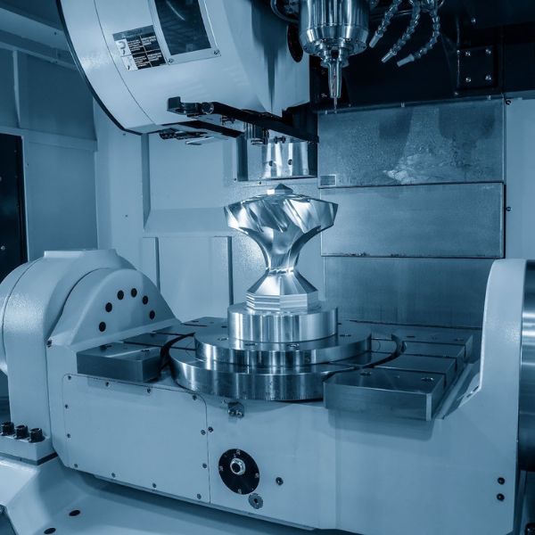
They are not interchangeable with a completed collision study. The CAM simulation must include the actual holder, cutter, fixture, part stock, rotary-axis limits, and postprocessor output. The resulting record should show how the selected orientations avoid collisions and whether the planned operations stay inside the usable envelope.
Turn-mill operations for blade roots
The five-axis turn-mill specification lists aircraft blade roots among its machinable parts. It lists maximum machining diameters of 400 mm, 650 mm, and 750 mm, maximum machining lengths of 1000/2000 mm, 1000-5000 mm, and 1000-6000 mm, and Y-axis travels of 240(+/-120) mm, 300(+/-150) mm, and 600(+/-300) mm. It also lists milling-spindle maximum speeds of 12000 rpm, 12000 rpm, and 6000 rpm, with rated torques of 70 Nm, 110 Nm, and 340 Nm.
Those values can help screen a blade-root or other rotational-feature concept for machine fit. They do not replace a part-specific chucking, support, tool-access, balancing, or inspection review. Where an engine component is the main subject, consult the separate CNC machining for aerospace engine parts article rather than turning this application guide into an engine-specialist chapter.
Process control from setup to inspection
Aerospace process control is strongest when the plan can be audited from the first setup through final inspection. Five-axis motion increases the number of possible orientations, so the process record should make the chosen orientations understandable to someone who did not program the original job.
Datum strategy and fixturing
Start with the functional datums and identify which of them must remain accessible for probing or inspection. The fixture should support the part without masking the features that establish the coordinate system. For thin or flexible sections, document support points and the sequence in which clamps are engaged and released.
The setup sheet should include part orientation, fixture reference, stock condition, tool list, probing routine, and the surfaces left for finishing. It should also identify any feature that cannot be measured in the same setup. That limitation matters when deciding whether a claimed setup reduction is actually beneficial.
Before release, review the setup as a sequence rather than as a single fixture drawing. The roughing state may need more support than the finishing state, and a clamp that is acceptable for material removal may obstruct a critical inspection feature later. The process record should show when support changes, what reference is retained after each change, and which surfaces remain intentionally unfinished. This makes the setup logic reviewable by programming, quality, and production teams.
The same review should cover the handoff between programming and the shop floor. The operator needs the approved coordinate system, tool identifiers, probing instructions, stock assumptions, and a clear response when a check is outside the expected condition. The programmer needs feedback about actual fixturing, tool wear, and measured results. Without that loop, a carefully simulated path can still be run under a different physical condition than the one used for verification.
Toolpath verification and compensation
Toolpath verification should cover gouge, collision, overtravel, holder clearance, and rotary-axis behavior. If a compensation or smoothing strategy is used, the record should explain which error it addresses and how the result is checked. A sentence such as “the machine compensates the error” is not enough without the measured feature, method, and acceptance criterion.
Near a thin wall or blended transition, the toolpath should be reviewed for sudden orientation changes, excessive engagement, and unsupported material. The process engineer can then choose between a continuous orientation change, an indexed operation, or a different tool and fixture strategy.
Surface quality and inspection records
Surface quality is a combined outcome of tool condition, engagement, feed, speed, coolant, rigidity, material behavior, and toolpath continuity. Record the inspection method and the actual measured result rather than using “high quality” as a substitute for evidence.
The inspection record should identify the datum reference, instrument or method, feature measured, result, and disposition. If a surface is functionally important, its acceptance requirement should be tied to the drawing, customer specification, or approved process document. This makes the result traceable and prevents a visual finish judgement from being mistaken for dimensional verification.
How to evaluate a five-axis aerospace machining partner
A capable partner should be able to explain the complete chain from design review to inspection. Ask for evidence of the following:
- The machine's usable travel, rotary range, table or chuck limits, spindle and tool capacity, and current calibration status.
- A setup and datum plan showing how the part is supported and how critical references are re-established.
- CAM verification that includes the actual holder, fixture, stock, postprocessor, and rotary-axis limits.
- A tool and process plan that addresses material behavior, wear monitoring, coolant, and surface integrity.
- Inspection records that identify the reference system, measured features, method, results, and nonconformance disposition.
- A clear boundary between documented machine capability and part-specific performance that still needs validation.
For broader industry context, see the site's aerospace industry solutions page. It is an industry solution page, not a substitute for the part drawing, process specification, or inspection report.
Summary
5-axis machining in aerospace manufacturing is most valuable when geometry, access, setup, and inspection are planned as one system. Aerospace structural parts machining benefits from deliberate support and datum control. Titanium alloy aerospace machining requires attention to tool wear, heat, engagement, and surface integrity. A machine specification can support an initial fit check, but the final process decision needs part-specific programming, workholding, verification, and inspection evidence.
The practical standard is traceability: every critical surface should have a datum, every orientation should have a reason, every numerical capability claim should have a source, and every acceptance decision should have a record.
A review should also distinguish repeatability from accuracy. A machine can return to a commanded position consistently while still carrying a systematic geometric, thermal, or calibration error. That is why the inspection plan should identify the test method, environmental conditions, axis or feature measured, and the point at which compensation is accepted. This distinction is especially important when a specification is used for early machine screening rather than final part approval.
A second useful distinction is between access and productivity. Five-axis access may reduce reorientation work, but it can also introduce more demanding simulation, postprocessor, and fixture requirements. The best process is the one that produces a controlled, inspectable result with a documented sequence, whether the selected operations use simultaneous motion, indexed positioning, or both.
Request a process review
If you are evaluating a complex aerospace component, share the material, envelope, critical datums, feature directions, and inspection requirements with the aerospace machining team. A process review can then determine whether five-axis milling, indexed work, turn-mill operations, or a combination is appropriate for the part.
References
- Analysis of Secondary Adhesion Wear Mechanism on Hard Machining of Titanium Aerospace Alloy — Supports the discussion of titanium alloy machinability and adhesion wear.
- Geometric Accuracy, Volumetric Accuracy and Compensation of CNC Machine Tools — Supports the distinction between machine accuracy, repeatability, geometric error, and compensation in process verification.
- Improvement in the efficiency of the five-axis machining of aerospace blisks — Supports the application context of complex aerospace blisk machining and the need for advanced process planning.