
Crankshaft milling uses either an internal ring cutter with inward-facing cutting edges or an external disc cutter with outward-facing cutting edges. Both can machine crankpin journals. The choice depends on cutter access, workpiece support, cutting conditions and the cost of producing an accepted crankshaft. Neither process name establishes a universal advantage in accuracy or cost. Published patents describe different benefits for particular designs. [1][2]
For process engineers and equipment buyers, the useful comparison starts with the same crankshaft drawing and blank. Compare the complete machining route, including the allowance left for later operations. A higher cutting speed or a larger cutter tells you little about the finished part unless the workholding, tool condition and acceptance measurements are also defined.
Key takeaways
- Internal milling and external milling describe cutter geometry, not a guaranteed quality ranking.
- Internal milling can use a stationary crankshaft or a rotating crankshaft, with different axis requirements.
- Compare support and cutter clearance at each journal, then verify the proposed cycle on a representative blank.
- Evaluate cost per accepted part. State the baseline before quoting any percentage saving.
Table of Contents
- Crankshaft milling motion and cutter geometry
- Workholding and access for crankpin milling
- Comparing internal milling and external milling
- Quality in the crankshaft machining process
- Cycle time and cost per crankshaft
- Selection and acceptance checklist
- Frequently asked questions
- Choose the process around the finished crankshaft
Crankshaft milling motion and cutter geometry
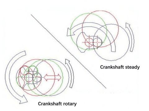
Internal milling with a stationary or rotating crankshaft
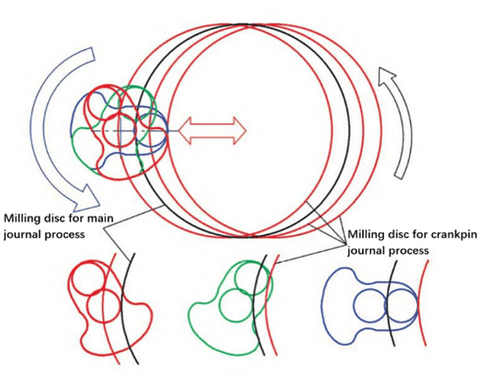
An internal milling cutter surrounds the journal with an annular body. Its cutting edges face inward. With a stationary crankshaft, the rotating cutter moves around the journal. With a rotating crankshaft, a design can coordinate the workpiece C axis with transverse cutter motion. US6283687B1 and EP3493935A1 describe these alternatives; they should not be treated as one machine layout. [1][2]
This distinction matters when you compare control requirements. Ask the supplier to show the motions used for a main journal and an eccentric crankpin. Identify which axes move during cutting, which axes position between journals, and how a change in crankpin phase affects the cycle. A machine animation should show the full operation, including entry, withdrawal and loading clearance.
External milling with a disc cutter
An external milling cutter contacts the journal from outside. For an eccentric crankpin, the machine must coordinate the cutter position with the workpiece motion. The detailed crankshaft high-speed external milling guide explains this tracking mechanism and the difference between external milling, turning and turn-broaching. The present comparison focuses on choosing a route and specifying its acceptance evidence.
US6684500B1 discusses combining machining methods for different bearing locations on a crankshaft. That is a useful reminder that a production route need not use one process for every surface. A proposal may use milling on crankpins and another operation on main journals or other features. The buyer should assess the route surface by surface rather than buy a process label. [4]
Workholding and access for crankpin milling
The cutter must reach the journal without preventing support where the crankshaft needs it. Ask for a layout that shows the chucks, support contacts, cutter envelope and workpiece. Check the complete travel, not only the position shown in a sales illustration. Loading clearance and tool replacement can determine whether an otherwise suitable layout works in production.
Check support at the cutting position
Compare where each proposed machine supports the crankshaft while cutting the same journal. Record the support contact position, the surface being contacted and the loading sequence. Ask how the machine accommodates blank variation before that support surface has been finish-machined. These are acceptance questions, not assumptions that one cutter type always permits better support.
Request the sequence for the journals nearest the chucks as well as those near the middle. A general layout drawing can hide a difficult cutter approach at one end of the part. It can also hide a support that must move before another journal is cut. Those movements belong in the cycle-time estimate and should be demonstrated with the actual workpiece envelope.
Separate a design limitation from a process limitation
EP0097271A1 addresses chuck-neck length, support and chip deposition in an internal milling machine. Its proposed design seeks to reduce the chuck overhang needed for cutter clearance. The existence of that design does not establish its performance on your crankshaft, but it does show why an old layout limitation should not be applied to every internal milling machine. [3]
A stiffness comparison needs its own test conditions. Ask where the load was applied, where displacement was measured, whether the fixture and workpiece were included, and what tool position was tested. A static displacement result does not by itself establish the roundness, tool life or vibration behavior of the complete production process. Evaluate those outcomes through the acceptance measurements they require.
Comparing internal milling and external milling
Use the following table to structure a supplier discussion. It identifies questions to resolve rather than assigning a general winner. The motion descriptions follow the cited patents; the evidence requests are a purchasing checklist. [1][2][3]
| Comparison point | Internal milling | External milling | Evidence to request |
|---|---|---|---|
| Cutter engagement | The journal is inside an inward-cutting ring | An outward-cutting disc approaches from outside | Cutter envelope and toolpath for each journal |
| Workpiece motion | May use a stationary or rotating crankshaft | The proposed crankpin cycle must show its coordinated motions | Axis sequence and phase-control method |
| Workpiece support | Clearance must be checked around the ring and support arrangement | Clearance must be checked between the disc, workpiece and supports | Layout through the complete cutting and loading cycle |
| Chip removal | Assess the actual enclosure, bed and chip route | Assess the actual enclosure, bed and chip route | Demonstration under the proposed cutting conditions |
| Tool servicing | Access depends on the ring, insert layout and machine structure | Access depends on the disc, insert layout and machine structure | Timed insert-change and cutter-change procedure |
| Economics | Evaluate the proposed machine and tooling | Evaluate the proposed machine and tooling | Cost per accepted part under one set of assumptions |
Chip removal and thermal behavior
EP3493935A1 describes a sloping internal-milling machine bed intended to reduce the time hot chips remain on the mounting surface. This is a design measure against heat entering the machine structure. It does not support a blanket claim that internal milling always accumulates heat or that external milling eliminates thermal effects. [2]
For either proposal, request the cutting and chip-removal conditions used to establish quality. Specify how the machine condition is recorded at the start and during a sustained run. Ask whether the acceptance measurements cover the required operating state, and whether an insert change or interruption changes the result. Evaluate the chip route as part of the proposed machine, rather than infer it from cutter geometry alone.
Cutting speed and chip thickness
US6283687B1 discusses high-speed milling at 350–500 m/min and reports a chip-thickness range of 0.05–0.4 mm, particularly 0.1–0.2 mm, for the tests described there. These are figures from that patent, not UBright production measurements, universal setpoints or proof that external milling produces a fixed percentage improvement. [1]
Use a quoted range as the start of a technical question. Ask which workpiece material, insert geometry and cutting arrangement apply to the proposed process. Ask whether the stated chip thickness is an average or maximum value and how it is determined. Keep the cutting-speed comparison separate from the full-cycle comparison. A process still has to load, position, support and unload the workpiece.
Quality in the crankshaft machining process
Specify the required condition after milling and the required condition of the finished crankshaft. These are different acceptance points. US6283687B1 describes a conventional route with rough machining, hardening and later grinding. A rough-milling comparison should therefore state the allowance and condition delivered to the next operation. The crankshaft following grinding article explains the downstream grinding process. [1]
Compare the same feature under the same conditions
A statement such as “better accuracy” needs a defined characteristic. Diameter, roundness, axial location and surface roughness describe different properties. Ask for separate results for the main journals and crankpins that matter on your drawing. Define the measurement method and the required part condition before choosing a machine on a headline figure.
| Characteristic | Define before a trial | Compare after the trial |
|---|---|---|
| Journal diameter | Feature, drawing limit, temperature condition and gauge method | Results against the same limit and measurement method |
| Roundness | Journal, measurement location and evaluation method | Recorded roundness results, not a general accuracy claim |
| Axial dimensions | Datum scheme and the features included | Results against the agreed datum scheme |
| Surface roughness | Surface, parameter and measurement conditions | Measured values with the same parameter and conditions |
| Downstream allowance | Requirement of the following operation | Delivered allowance and its variation |
| Process stability | Run conditions, tool condition and sampling plan | Results through the agreed run and tool changes |
Agree on the record that accompanies each measured part. It should identify the feature, process condition and tool condition, so a favorable result can be connected to the cycle that produced it. Require the same records for both proposals. Mixing a fresh-tool result from one route with an extended-run result from another prevents a useful comparison even when both numbers are accurate.
Avoid turning a range into one improvement percentage
If two routes are described by ranges, request the underlying observations before quoting a percentage improvement. Comparing the best result from one range with the worst from the other is not a paired trial. Comparing midpoints without stating that method is also insufficient. Use the agreed drawing requirements and recorded results to decide whether each route delivers accepted parts.
The same principle applies to stiffness diagrams and cutter engagement calculations. Keep their geometry, load and boundary conditions attached to the result. A displacement or contact-length value from one arrangement is evidence about that arrangement. It cannot replace a machining trial on a different machine, fixture, cutter and crankshaft.
Cycle time and cost per crankshaft
Define the complete cycle
Create one cycle-time worksheet for both proposals. Separate loading, positioning, cutting, cutter withdrawal, unloading and any agreed inspection. Record which tasks overlap and which must happen in sequence. A cutting-only estimate cannot be compared directly with a complete automatic cycle.
Ask for the cycle on the same blank condition and finished milling requirement. If one proposal leaves more material for grinding, its faster milling cycle may move work to another operation. Evaluate that change in the route cost and capacity plan. Do not count a reduction in one operation as a saving for the complete line before the remaining operations are assessed.
Include tool changes and accepted output
A short trial with new inserts may establish that the machine can perform the cut. It does not establish tooling cost over the intended production period. Request the assumptions for insert use, cutter servicing, change time and the parts accepted between planned interventions. Distinguish an observed trial result from a supplier estimate wherever either appears in the worksheet.
| Cost element | Information to record | Comparison rule |
|---|---|---|
| Machine and installation | Scope, included equipment and cost assumptions | Compare equivalent installed scope |
| Operating time | Full cycle and planned production time | Use the same basis for productive time |
| Tooling | Insert use, cutter servicing and change procedure | State the cost and accepted output basis |
| Rejected or reworked parts | Acceptance criteria and recorded outcomes | Include their agreed cost treatment |
| Following operations | Allowance and work passed to the next operation | Assess the complete machining route |
| Maintenance and changeover | Planned interventions and part-family changes | Separate observed times from estimates |
Keep the cost baseline explicit
An arithmetic example shows why the denominator matters. Suppose an internal route costs 125 currency units per accepted part and an external route costs 100. The internal route is 25% more expensive relative to the external route. The external route is 20% cheaper relative to the internal route. These are hypothetical values illustrating the calculation, not quoted machine costs or measured process savings.
EP3493935A1 argues for lower machining cost with its internal-cutter concept, while US6283687B1 discusses tool life and machining costs in its proposed process. These documents present design arguments, not a neutral price survey. Use them to identify the cost drivers to investigate. Obtain project-specific evidence before claiming that either milling process is always cheaper. [1][2]
Selection and acceptance checklist
Use this sequence before comparing final quotations. The aim is a proposal that can be checked against a drawing, demonstrated on a representative workpiece and evaluated as part of the production route.
- Define the part family. Supply the drawings and blank requirements for the crankshafts included in the decision. Identify which journals, webs and adjacent surfaces are in scope. State the expected part changes instead of assuming the initial part represents the entire family.
- Define the machining boundary. List what the milling machine receives and what it must deliver. Include the allowance and condition required by the following operations. Identify any feature assigned to turning, turn-broaching or another process.
- Review the complete layout. Check chucking, support positions, cutter travel, loading clearance and tool-service access. Ask for the difficult end-journal cycle and the transitions between crankpins, not only a central-journal illustration.
- Agree on the trial conditions. Specify the representative blank, cutter and inserts, tool condition, operating state, run scope and measurement plan. Ask the supplier to identify estimates separately from demonstrated results.
- Record the full cycle. Time the agreed operations and interruptions. Record overlapping tasks clearly. Compare accepted output under the same operating assumptions rather than compare isolated cutting speeds.
- Measure the delivered part. Apply the drawing limits and measurement methods agreed before the trial. Check the allowance for later operations as well as the milling results. Retain results through the agreed run and tool changes.
- Build a cost worksheet. Use the same installed scope, productive-time basis and treatment of rejected parts. Show tool servicing, changeover and downstream work. Label any hypothetical calculation so it cannot be mistaken for measured performance.
- Write the acceptance record into the purchase scope. State which results must be demonstrated and what information accompanies them. Resolve differences in scope before accepting a comparison percentage or selecting the proposed process.
For a line-level review, the crankshaft manufacturing solutions page provides the route context. Use the process comparison to decide where milling belongs in that route, rather than treat the milling machine as an isolated investment.
Frequently asked questions
Is external milling always more accurate than internal milling?
No universal ranking follows from the process name. Compare the proposed machines on the same crankshaft and drawing limits. Workholding, cutter condition, operating state and the measurement method belong in the acceptance record. Published patents discuss different design advantages; they do not establish that every external milling machine outperforms every internal milling machine. [1][2]
Does internal milling require a stationary crankshaft?
No. The cited patents describe stationary-workpiece internal milling and internal milling with a rotating workpiece. In the rotating design, cutter motion must be coordinated with the workpiece rotation. Ask for the actual axis sequence used on an eccentric crankpin, because those two arrangements have different motion and clearance requirements. [1][2]
Can a higher cutting speed prove a shorter production cycle?
It cannot establish the complete cycle on its own. Cutting time is only part of loading, positioning, supporting, machining and unloading. Tool changes and the work passed to following operations also affect accepted output. Require both proposals to report the same cycle boundary before comparing their time estimates or demonstrated results.
Should a fixed machining-allowance threshold decide the process?
Use the specified blank, workpiece geometry and proposed tooling to assess suitability. A fixed threshold without a documented process basis is insufficient. Ask each supplier to demonstrate the required allowance removal and delivered condition on the representative crankshaft. Evaluate cutter access, support, tool use and following operations as part of that trial.
Does milling remove the need for grinding?
That depends on the production route and final requirements. The conventional route described in US6283687B1 includes later grinding after rough machining and hardening. A milling proposal should state the condition it delivers to the following operation. Do not infer that grinding can be removed from a rough-milling comparison or an unverified accuracy table. [1]
Choose the process around the finished crankshaft
Crankshaft milling should be selected through a defined part, a demonstrated layout and an acceptance record. Choose the internal milling or external milling proposal that meets the required condition at an acceptable route cost. Keep supplier estimates, patent examples and measured trial results separate throughout the decision.
For a review of your crankshaft drawing, blank condition and production route, contact UBright Solutions. Include the part family, machining scope, downstream allowance requirements and planned output so the discussion starts with the conditions the equipment must meet.
References
- US6283687B1: Multiple milling on crankshafts — Internal and external cutter geometry, machining motions, stated high-speed milling conditions and the conventional rough-machining-to-grinding route.
- EP3493935A1: Internal milling machine — Stationary and rotating internal-milling concepts, the proposed bed and chip-removal arrangement, and the patent's internal-cutter cost argument.
- EP0097271A1: Crankshaft milling machine — Internal-milling design measures addressing chuck-neck length, workpiece clearance and chip deposition.
- US6684500B1: High speed milling and turning/turn broaching/turning and turn broaching — Combining machining methods for different crankshaft bearing locations.