
An automatic straightening machine is not a manual straightener with a feeder bolted onto it. To run unattended on hardened fasteners, the machine has to solve three problems that a hand-fed straightener leaves to the operator: present parts one at a time, decide which way each individual part is bent before applying any force, and move the finished part out without putting bend back into it.
That second problem is the one that defines the machine class. Everything else — hydraulics, rollers, racks — exists on manual equipment too.
Everything below is drawn from one real build: a bolt straightening line supplied to a fastener manufacturer in India, and specifically from its technical agreement, its equipment specification and the customer’s own part drawings. Where a number appears, it is that line’s number, not a catalogue figure.
Table of Contents
- What an Automatic Straightening Machine Actually Includes
- Direction Discrimination Is What Makes It Automatic
- How the Two-Roller Hydraulic Mechanism Removes Bend
- Where One Machine Class Stops
- Holding the Setting Through a 24-Hour Duty Cycle
- Site Conditions That Bind the Installation
- How an Automatic Straightening Machine Gets Accepted
- Questions From the Shop Floor
Key Takeaways
– The functional difference between a powered straightener and an automatic straightening machine is automatic discrimination of straightening direction — without it, unattended running can add bend instead of removing it. – The automatic straightening machine described here ships as four units, not one: straightener, infeed rack, outfeed rack and gripper arm, fed by a push-plate loader. – One machine class does not cover a full fastener range. The two-roller hydraulic machine on this line covers Ø10–14 mm at ≤0.1–0.15 mm; the smaller Ø6–8 mm family needed a different class at 0.15–0.25 mm, and that class leaves roller marks. – Acceptance is a two-stage protocol, and the final stage is one week of continuous fault-free production at the end user’s site, not a factory demonstration.
What an Automatic Straightening Machine Actually Includes
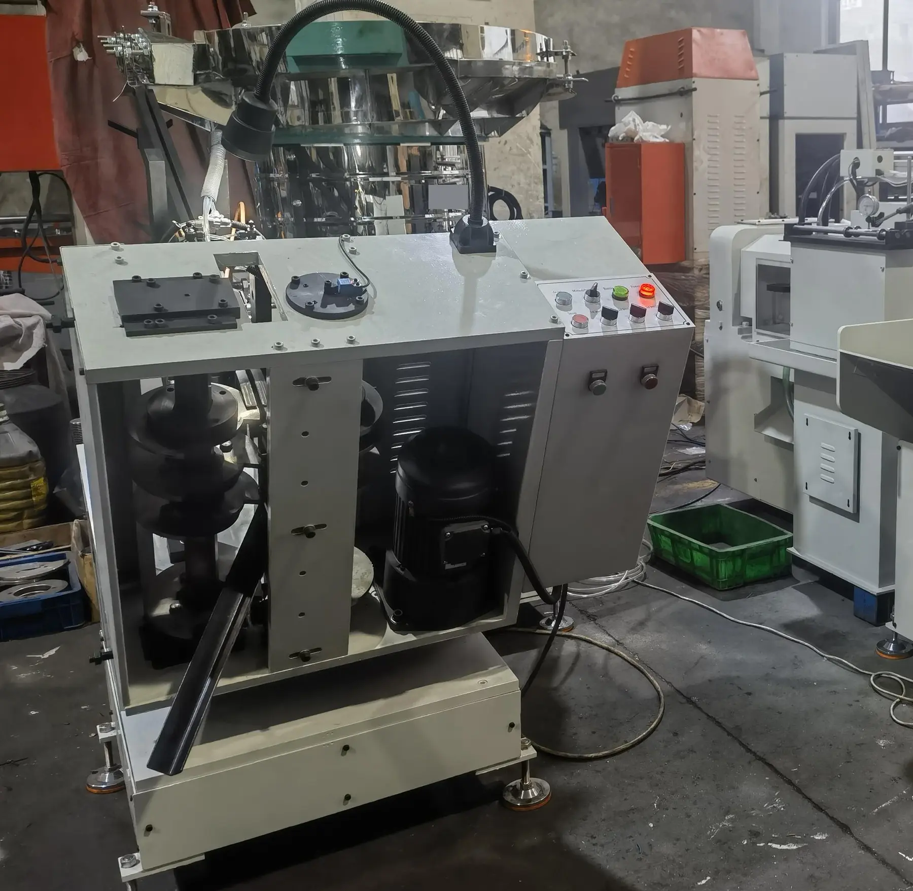
In the technical agreement for this line, the scope of supply is written as four separate units rather than one machine: the straightening machine itself, an infeed rack for presenting workpieces, an outfeed rack for receiving them, and a gripper arm for picking parts up. A push-plate loader feeds the straightener, and a 1.2 m vibratory bowl was quoted alongside it for bulk orientation of smaller parts.
That split matters when you are comparing quotations. A line item that says “automatic straightening machine” can mean the straightening head alone, with the handling left as a separate integration problem. Here the handling units are named individually, each with its stated purpose, which is what makes the scope checkable at acceptance rather than arguable.
The reason a bolt needs this much handling is geometric, and the supply scope shows it directly. A headed fastener is short relative to its diameter, asymmetric end to end, and arrives in a bin at a random rotational angle. A bar straightener can pull continuous stock through rollers because the stock is effectively infinite and self-aligning. Even a slender shaft is easier to handle than a bolt, which is why straightening a camshaft is a different problem with a different fixture: the part is long enough to support at two points and orient by its own features. A bolt has to be singulated, oriented, driven through, and caught — which is exactly why this agreement lists a vibratory bowl, a push-plate loader, an infeed rack, a gripper arm and an outfeed rack as separate line items for parts only 90 to 325 mm long. Five handling elements for a part shorter than a ruler is not over-specification; it is what the geometry costs.
Laid out in sequence, the scope of supply is a handling chain with the straightening head as one station inside it:
flowchart LR
    A["Vibratory bowl"] --> B["Push-plate loader"]
    B --> C["Infeed rack"]
    C --> D["Direction discrimination"]
    D --> E["Two-roller straightening"]
    E --> F["Gripper arm"]
    F --> G["Outfeed rack"]
Only one of those seven stations is the straightener. When a quotation prices “the machine”, it is worth asking which of the other six it includes.
Direction Discrimination Is What Makes It Automatic
A bent bar is not uniformly bent. It has a high side. Straightening works by applying force against that high side, which means the machine has to know where it is before it closes on the part.
An operator working a manual straightener solves this by rolling the part against an indicator or a flat, finding the high point by eye or by dial reading, and then positioning it before applying pressure. That step is judgement, and it is repeated on every part. It is also the step that makes manual straightening slow and operator-dependent.
The specification for this machine requires it to discriminate the straightening direction by itself so that processing runs automatically. That single clause is the functional core of the machine class. Without it, an automated feeder is actively dangerous to quality: parts arriving at random rotational angles get force applied at random angles relative to their bend, and a proportion of them leave the machine more bent than they entered. Feed automation without direction discrimination does not produce an automatic straightener. It produces a fast way to make scrap.
This is also why the loader type is specified rather than left open. A push-plate loader presents the part in a controlled attitude to the rollers, which is the precondition for the machine to resolve bend direction at all.
How the Two-Roller Hydraulic Mechanism Removes Bend
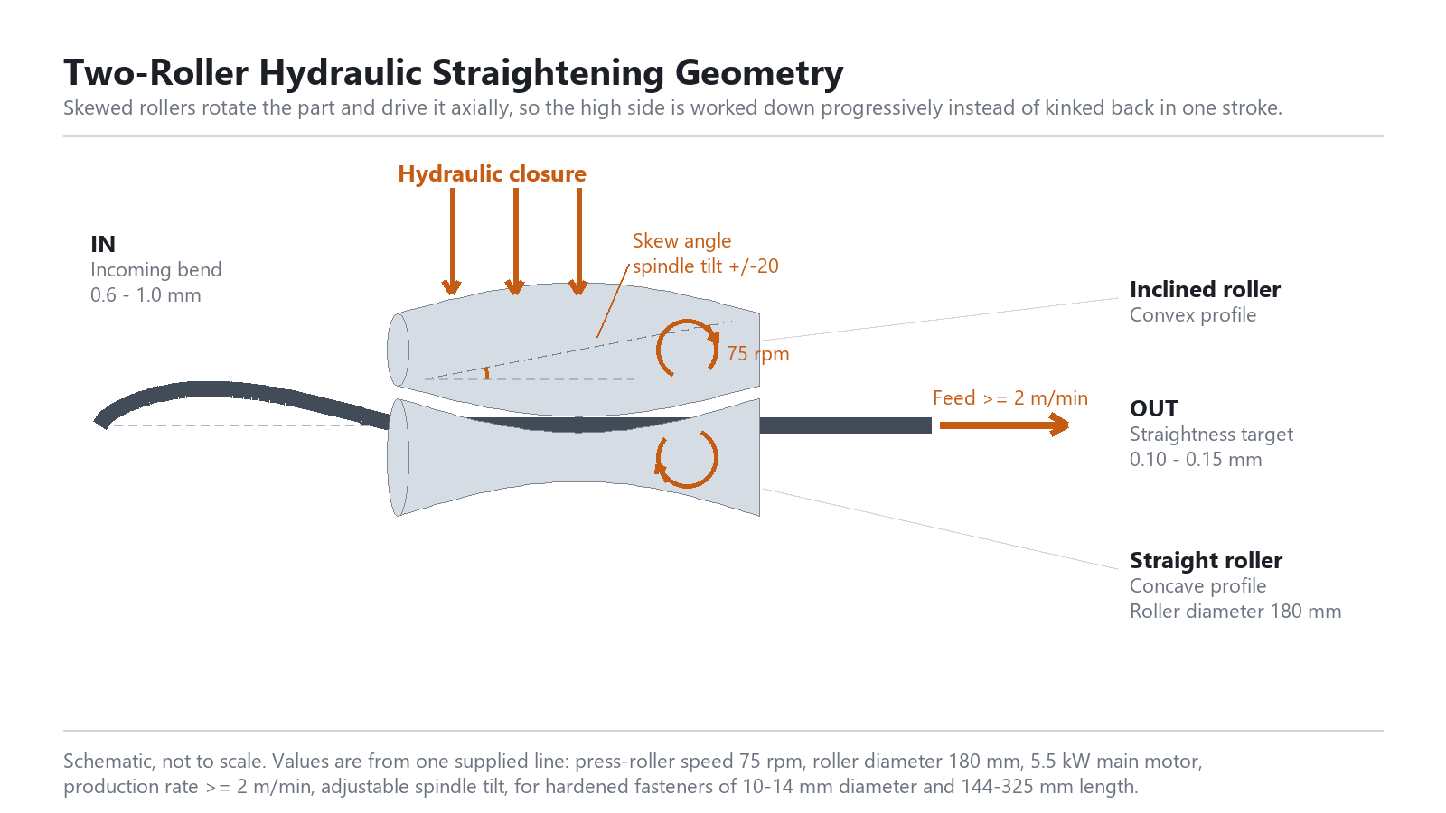
The machine on this line is a two-roller hydraulic straightener. The press-roller mechanism pairs an inclined roller carrying a convex profile against a straight roller carrying a concave profile, and hydraulic pressure closes the gap between them onto the workpiece.
The mechanism works by rotation, not by a single press stroke. Because the roller axes are skewed relative to the part axis — the spindle tilt is adjustable through ±20 on this machine — the rotating part is also driven axially and feeds itself through the gap. Each rotation brings a different angular position of the part into the loaded zone. The high side is worked down repeatedly and progressively rather than kinked back in one hit, which is what distributes the correction along the length instead of concentrating it at one point.
That progressive action is why throughput on this class is expressed as a linear rate rather than a parts-per-minute count. The specification records a press-roller speed of 75 rpm, a roller diameter of Ø180 mm, a production rate of ≥2 m/min and a 5.5 kW main motor with a 40 W cooling pump. A part is in the machine for as long as its own length takes to pass through, so a 325 mm part and a 144 mm part do not cost the same cycle time.
The geometry below shows why the skew is doing two jobs at once — closing on the bend, and feeding the part through:
Straightening also sits at a specific point in the fastener process chain. On the customer’s own part drawings for this line, straightening follows heat treatment and precedes hard rolling and grinding:
flowchart LR
    A["Heat treatment"] -->|"introduces distortion"| B["Straightening"]
    B -->|"part must run true"| C["Hard rolling"]
    C --> D["Grinding"]
That order is not arbitrary: heat treatment is where the distortion is introduced, so straightening has to come after it, and it has to come before the finishing operations that depend on the part running true. The same sequence shows up on other hardened slender parts — on an EPS worm shaft the straightening step likewise sits between heat treatment and the operations that set final runout. We have written separately about how that route is split by part size and verified at each step in the high-strength bolt straightening process; this article stays on the machine rather than the route.
Where One Machine Class Stops
The most useful thing this build shows is a boundary, not a capability. The full fastener range could not be covered by one automatic straightening machine.
| Part family | Diameter | Length | Post-straightening straightness | Machine class |
|---|---|---|---|---|
| Larger group | Ø10–14 mm | 144–325 mm | ≤0.1–0.15 mm | Two-roller hydraulic, automatic |
| Smaller group | Ø6–8 mm | 90–219 mm | 0.15–0.25 mm | Vertical straightening machine |
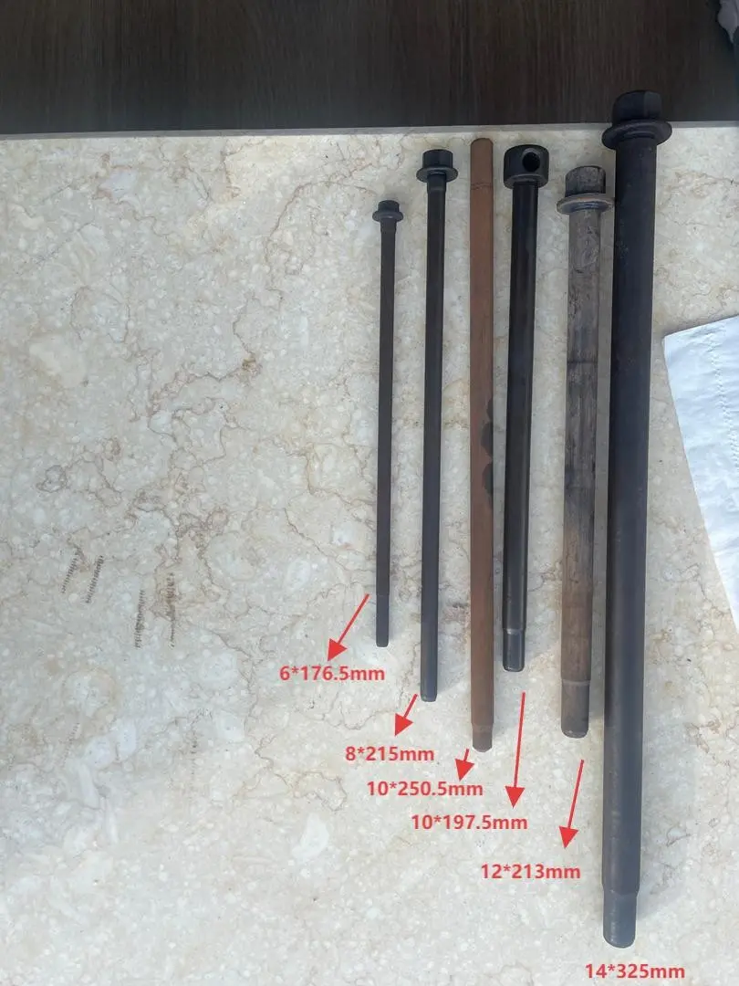
The sample set for this line runs from 6 × 176.5 mm at one end to 14 × 325 mm at the other. Laid side by side, the length-to-diameter spread is the whole reason two machine classes were needed.
Two things force the split. The first is the tolerance band: the smaller family is held to 0.15–0.25 mm while the larger family is held to the tighter 0.1–0.15 mm, and the classes are not interchangeable across those bands.
The second is a surface trade-off that is easy to miss in a specification review. The vertical class used for the smaller family leaves roller marks on the workpiece. The customer’s requirement sheet prohibits roller marks in the straightening operation for both families, and for the smaller family it goes further: straightening is to be done after surface treatment, with no lubrication and no marking permitted. That conflict was real, and it had to be resolved as an accepted deviation before the machine could be signed off — not discovered during commissioning. If your drawing carries a surface condition alongside a straightness number, check it against the machine class before the tolerance discussion starts, because a class that reaches the number may not reach it cleanly.
The parts on this line are high-strength fasteners running property class 8.8 through 12.9 — the smallest size, M6, starts at 9.8 — in SAE 1541 and SAE 4140, with SAE 15B25 added on the larger family. Property classes are defined in ISO 898-1; the SAE alloy steel designations are covered by SAE J404. Hardness matters here because a harder part springs back more, and springback is what the straightening pass has to overshoot to land inside the band. That is the physical reason the tighter 0.1–0.15 mm requirement on this project landed on the machine class with hydraulic closure and a lockable feed setting rather than on the class that was adequate for the looser 0.15–0.25 mm group.
The requirement sheet also fixes the other end of the job, which is the part that gets left out of most straightening specifications: how bent the parts are allowed to be arriving. Both families are accepted with 0.6 to 1.0 mm of incoming bend. That single shared input condition is what makes the output split meaningful — the same 1.0 mm of bow has to come out to 0.15–0.25 mm on the smaller family and to 0.1–0.15 mm on the larger one. The harder job is the larger part: take up to 1.0 mm of bow out of a hardened Ø14 shank and land it inside a 0.05 mm-wide window. A straightening quotation that states an output tolerance without an input condition has specified half the problem.
Holding the Setting Through a 24-Hour Duty Cycle
The duty requirement in the technical agreement is explicit: continuous operation 24 hours a day, no fewer than 20 days a month, with accuracy retained long-term rather than at handover only.
Two design details in the specification exist to meet that. The feed structure is handwheel-adjusted and lockable, so an operator-set position cannot walk under vibration across a long shift. The machine also uses a cross-type rotating shaft on the specified configuration.
The consumables list is the other half of the answer, and it changes how a size change should be planned. The agreement lists two blade plates and one pair of rollers as supplied wear items, both explicitly configured according to workpiece specification. Changing part family on this machine is therefore a tooling change, not only a setting change. Any cycle-time or changeover estimate that assumes a knob turn between sizes will be wrong on a machine specified this way.
Site Conditions That Bind the Installation
An automatic straightening machine going to an export destination carries a set of site conditions that belong in the purchase agreement, because they are cheaper to specify than to retrofit after the automatic straightening machine has already shipped.
| Condition | Requirement on this line |
|---|---|
| Supply | Three-phase 415 V ±10%, 50 Hz ±2%, three-phase three-wire |
| Control circuit | Independent isolation transformer, matched to the destination country’s supply system |
| Compressed air | 0.5–0.6 MPa |
| Ambient humidity | ≤90% RH at 20 °C |
| Noise | ≤80 dB |
The isolation transformer requirement is worth reading closely. It appears in the general agreement as an independent transformer suited to the destination supply, and it was later refined in project correspondence to a 440 V to 220 V step-down arrangement for the control circuit specifically, on the grounds that the existing neutral connection was not in use and a step-down isolation arrangement avoids leakage. A control circuit referenced to a neutral that the installation does not actually use is a commissioning problem discovered at the far end of a sea shipment. IEC 60204-1 is the general requirements standard for electrical equipment of machines and is the right reference point for that conversation with a supplier.
The agreement also carries a packaging clause that reads as boilerplate until you have received a rusted machine: fumigated wooden crates strong enough for repeated lifting, all fluids drained before dispatch, and sufficient anti-corrosion oil on every metal surface. On a long sea route into a humid climate, that clause is the difference between a machine that commissions and one that arrives with moisture in the electrical enclosures.
How an Automatic Straightening Machine Gets Accepted
The acceptance protocol for this automatic straightening machine is two-stage, and the second stage is the one that carries weight.
Pre-acceptance, at the supplier’s works. The supplier gives 15 days’ written notice before the machine is ready. The buyer then checks the scope of supply item by item against the agreement, inspects appearance, configuration and documentation, and witnesses static accuracy plus mechanical and electrical acceptance using instruments the supplier provides. The decisive item is trial machining: the machine runs the buyer’s own part drawings, and the cycle time has to meet the agreed parts cycle-time table. The acceptance parts then ship with the machine.
Final acceptance, at the end user’s site. Every pre-acceptance item is repeated, and then the machine has to run one week of continuous normal production without fault before the buyer’s technical staff will sign. Only after that does the supplier back up the complete machine dataset — system parameters, PLC parameters, axis and servo parameters, accuracy compensation values and the PLC ladder — to disc or USB, and the machine is declared in normal working state.
That structure is the part worth copying into your own RFQ. A factory acceptance test proves the machine can make a good part. A week of continuous production proves it can keep making them through an automatic feed cycle, which is the only claim that matters on an automatic straightening machine.
Straightness itself is verified with straightness gauges fitted with dial indicators; two were specified as part of the delivered scope on the earlier machine in this project. Gauging hardware for fastener work is a precision product in its own right — the same holds for thread inspection, as our note on thread plug gauge grinding sets out. The related part drawing states the requirement as runout in the centre area of the supported interval staying within 0.060 mm over a 100 mm measured distance. For the gaging convention behind that kind of measurement on threaded parts, ASME B18.2.9 defines a gage and gaging procedure for bolt and screw straightness at maximum material condition.
The remaining commercial terms in the agreement round out what “accepted” means in practice: five working days of operator and maintenance training during pre-acceptance plus on-site training during commissioning, one year whole-machine warranty from on-site acceptance with an eight-hour response commitment, and 30 calendar days’ delivery from contract effect.
Questions From the Shop Floor
Does an automatic straightening machine remove the need for a straightness gauge?
No. Straightness gauges with dial indicators were specified as delivered items on the earlier machine supplied to this customer, which kept measurement as a separate instrumented step rather than something the straightener certified for itself. Direction discrimination tells the machine where the bend is on each part; it does not produce an acceptance record. Final acceptance still depended on measured straightness against a drawing requirement, and the machine’s own process control does not substitute for that measurement.
Can one automatic straightening machine cover M6 to M14?
Not on this line. The Ø10–14 mm family ran on the two-roller hydraulic automatic machine at ≤0.1–0.15 mm, and the Ø6–8 mm family needed a vertical straightening machine at 0.15–0.25 mm. Before assuming a single machine covers a range, check the tolerance band and the permitted surface condition at both ends of it, not just the diameter limits.
Why does the control circuit need its own isolation transformer?
Because the destination supply system may not match the assumptions the control circuit was built on. At this installation the existing neutral connection was not in use, and the resolution was a step-down isolation arrangement supplying the control circuit to avoid leakage. Specifying the transformer with the machine is cheaper than diagnosing it after the container is unpacked.
What should a changeover between part sizes actually involve?
On a machine specified like this one, more than a setting change. The blade plates and roller pair are supplied configured to workpiece specification, so moving between part families involves tooling as well as feed adjustment. Ask the supplier for the changeover sequence and its time before you build either into a capacity model.
Conclusion
The label “automatic straightening machine” covers a wide range of scope. What separates the real thing from a powered straightener with a feeder is whether the machine resolves bend direction on each part by itself, and whether the handling units, the wear tooling, the site conditions and the acceptance protocol are written down at the same level of detail as the straightness number.
On the line described here all four are written into one technical agreement, and it also shows the honest limit: one machine class covered part of the fastener range, and the rest needed a different class with a different surface outcome.
If you are specifying a straightening machine for a hardened fastener line and want the capability envelope and acceptance protocol checked against your own part drawings before you commit, our engineering team can review your drawings and straightness requirements with you.
References
- ISO 898-1:2013, Mechanical properties of fasteners made of carbon steel and alloy steel, Part 1 — defines the property class system behind the 8.8 to 12.9 designations carried on this line’s parts.
- ASME B18.2.9, Straightness Gage and Gaging for Bolts and Screws — specifies the gage and gaging procedure for bolt and screw straightness at maximum material condition.
- IEC 60204-1:2016, Safety of machinery, Electrical equipment of machines, Part 1: General requirements — the reference point for the control-circuit supply and isolation arrangement discussed under site conditions.
- SAE J404, Chemical Compositions of SAE Alloy Steels — covers the SAE 1541, SAE 4140 and SAE 15B25 alloy designations named in the requirement sheet.