
A steering knuckle machining process is difficult because one safety-critical part combines bearing seats, bores, faces, threaded features, and irregular arms that are referenced from different directions. The durable answer is not simply to add more axes. It is to build one controlled relationship among datum selection, workholding, tool access, process sequencing, and verification.
Automotive steering knuckle machining planning
Automotive steering knuckle machining must connect the part's functional interfaces to a stable datum and measurable process state. The following sections show how to connect the part's datums, supports, tool paths, and inspection evidence.
Key takeaways
- A steering knuckle is a multi-directional part, so datum strategy must tie each critical feature back to functional interfaces.
- Reducing re-clamps can reduce opportunities for reference transfer error, but only when the first setup is stable and measurable.
- Multi-axis access, support placement, cutting strategy, and tool-condition control are interdependent decisions.
- Process capability must be demonstrated on the actual part, fixture, tooling, program, and measurement system rather than inferred from a machine specification.
Table of Contents
- Automotive steering knuckle machining planning
- Why steering knuckles are difficult to machine
- What single setup machining really changes
- Build the steering knuckle machining process around functional datums
- Use multi-axis motion to reach features, not to hide weak workholding
- Design workholding around load paths and compliance
- Plan the cutting sequence and tool strategy together
- Verify the complete manufacturing system
- A practical planning checklist
- Frequently asked questions
- Conclusion
- References
Why steering knuckles are difficult to machine
A steering knuckle machining process is not a simple prismatic component with all features accessible from one face. Its geometry commonly combines a bearing or hub interface, steering-arm features, suspension connections, brake-related interfaces, and threaded or drilled details. Those features may face different directions and may have different functional datum relationships.
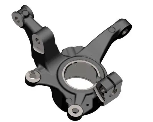
That geometry creates a process-planning problem before it creates a machine-selection problem. A planner has to answer four connected questions:
- Which surfaces or bores establish the functional coordinate system?
- Which material can safely absorb clamping and cutting loads before finish features are created?
- Which features must remain related without a new datum transfer?
- Where can a tool approach, retract, and clear the fixture throughout the programmed motion?
The source material for this article highlights the same underlying conflict: a complex knuckle can require several orientations, while each additional transfer creates another chance for locating variation, clamp-induced movement, handling damage, or an incomplete feature relationship. That is a useful engineering observation. It is not proof that every part should be machined in one clamping cycle.
The best process is the one that controls the part's critical relationships at the required volume, material condition, tolerance, and inspection cost. For one production program that may mean a highly integrated multi-axis setup. For another, two controlled setups with a deliberately machined transfer datum may be more robust.
What single setup machining really changes
Single setup machining means completing the planned set of features while the workpiece remains referenced by the same intentional locating scheme. It does not mean that every surface is machined without interruption, that every feature is cut by one tool, or that a part never moves relative to a fixture under load.
The main advantage is geometric continuity. When critical faces, holes, and bores are completed from one datum scheme, the process avoids re-establishing their relationship from a freshly clamped part. This can be particularly important when a feature on an arm, a bore on a hub region, and a face on another plane must maintain a controlled spatial relationship.
However, fewer setups only help if the original reference remains trustworthy. A one-setup process can fail when:
- an irregular forging or casting does not repeat reliably against its intended locators;
- clamp loads distort thin or unsupported regions;
- chips collect on a locating surface during a long cycle;
- a feature is finished before the part reaches a stable stress state;
- the fixture blocks a required tool vector or makes probing impossible;
- tool reach produces excessive deflection at a critical bore or face.
A useful planning rule is therefore: reduce datum transfers only after proving the first datum scheme, support scheme, and cutting sequence. Setup consolidation is an outcome of controlled process design, not a substitute for it.
Build the steering knuckle machining process around functional datums
A robust steering knuckle machining process begins with functional relationships, not with the available clamps. The drawing, assembly interfaces, and inspection plan should identify what the part must do when assembled. Those interfaces become the basis for a manufacturing datum strategy.
Separate manufacturing locators from finished functional datums
The raw workpiece often arrives as a casting or forging. Its available surfaces can be variable, and an as-cast or as-forged feature may be suitable for rough location without being suitable as the final manufacturing truth. The process should make that distinction explicit:
| Datum role | Typical purpose | Planning question |
|---|---|---|
| Rough location | Holds the incoming blank for opening operations | Does the variation leave enough machining stock and repeatable contact? |
| Process datum | Carries the part through related operations | Can the fixture repeat the location and resist the planned loads? |
| Functional datum | Controls final relationship to mating parts | Which finished features must be measured from it? |
| Inspection datum | Establishes the CMM or gauging coordinate system | Does it represent the functional requirement without masking process error? |
The fixture should constrain the degrees of freedom that matter for the operation while avoiding unnecessary over-constraint. In practical terms, that means locating pads, pins, nests, or surfaces must be chosen for stability, accessibility, chip evacuation, and measurement—not merely because they are convenient to reach.
Decide which features create the transfer reference
If a part needs more than one setup, the first setup should intentionally create the surfaces or bores used to locate the second. The second fixture then references a machined, measurable condition rather than relying again on variable raw stock. This does not eliminate error, but it makes the reference transfer explicit and inspectable.
For a more integrated approach, planners should map every critical feature to the same coordinate strategy. A feature matrix helps expose conflicts early:
| Feature group | Functional relationship | Access need | Process risk to evaluate |
|---|---|---|---|
| Bearing or hub region | Concentricity and face relationship | Axial tool access | Long-tool deflection; datum protection |
| Arm and linkage interfaces | Position and angular relationship | Side or tilted access | Fixture interference; local stiffness |
| Threaded and drilled details | Position relative to primary datums | Directed drill/tap access | Chip control; probe clearance |
| Brake or mounting faces | Flatness and spatial relation | Face-milling access | Clamp distortion; finishing order |
This matrix turns a vague requirement—“machine all sides accurately”—into a set of testable access and relationship decisions.
Use multi-axis motion to reach features, not to hide weak workholding
Multi-axis CNC motion can orient an irregular component so that a cutter approaches features along a favorable direction. It can also reduce manual reorientation and enable a planned sequence of machining vectors. For steering knuckles, that can be valuable when holes, faces, and bores exist on non-parallel planes.
The limitation is equally important: multi-axis motion does not correct a part that shifts in the fixture, a weak support under a cutting load, a poor datum choice, or an unstable tool path. The fixture and the machine are a coupled system.
Before committing to a multi-axis process, review these questions for every critical tool orientation:
- Can the cutter, holder, spindle, and probe clear the fixture and all non-cut regions of the part?
- Is the tool length appropriate for the expected force and tolerance requirement?
- Does the programmed orientation maintain adequate workholding support under the cutting force direction?
- Can coolant and chips leave the contact area instead of packing into locators or bores?
- Does the orientation create a collision-free recovery path if a tool breaks or a probe cycle stops?
Treat accessibility as a geometric check
Tool access should be checked in the CAM model with the actual fixture, clamps, supports, holder geometry, and stock condition. A nominal part-only simulation can approve a tool path that cannot physically run once the workholding is installed.
For parts with deep or angled features, accessibility should include the complete cutting envelope: entry, engagement, lead-out, retract, tool-change clearance, probing path, and operator load/unload path. A tool that technically reaches a bore but has no reliable retract path is not a production-ready solution.
Protect high-value finish operations
Finish bores, precision faces, and alignment features should normally be scheduled after the process has established a stable condition. This may require roughing while supports are fully active, semi-finishing after stress redistribution or a probe check, and finishing only after the fixture and program have met their repeatability criteria.
The exact sequence depends on material, stock condition, tolerance, and tool system. The universal principle is simpler: do not ask the finish tool to compensate for uncertainty introduced earlier in the same cycle.
Design workholding around load paths and compliance
Workholding is the mechanical link between the part, the cutting load, and the datum system. A fixture that locates the part well when idle can still allow movement or local distortion once the cut begins.
For an irregular knuckle, the fixture review should cover three load paths:
- Clamping load path — where force enters the part and where the opposing support carries it.
- Cutting load path — how the expected tool force travels through the local wall, arm, boss, or bore region to a rigid support.
- Reaction load path — whether the fixture base, locators, clamps, and machine interface remain stiff enough to preserve the reference condition.
A clamp placed far from a support can bend a thin arm. A support placed near a critical finishing region can block tool access. A clamp may also protect a part during roughing but create unacceptable distortion during face finishing. These are not separate fixture issues; they are trade-offs inside the same load path.
Use support where the cut demands it
Unsupported overhangs are a common source of vibration, surface deterioration, dimensional drift, and unpredictable tool life. When a feature lies on an arm or projection, consider whether an adjustable support, rest pad, or secondary contact can carry the local reaction force without over-constraining the part.
The support must be designed around the material condition and operation. A support that touches an inconsistent raw surface may introduce variability. A support that is activated after the part is already clamped may be appropriate only if its force is controlled and repeatable. These choices should be validated by measurement and process trials, not assumed from fixture drawings.
Make the fixture observable
A production fixture should allow the team to detect an incorrect seating condition rather than merely hope that it does not occur. Practical controls can include contact confirmation, probing of a reference feature, monitoring of clamp state, chip-clearing routines, and documented checks for locator wear.
The NIST/SEMATECH e-Handbook treats the measurement process itself as something that must be characterized before its results are relied on. That principle applies directly to fixturing: a fixture becomes more dependable when the process can detect whether the intended reference condition was actually achieved, instead of assuming it was.
Plan the cutting sequence and tool strategy together
The cutting plan should not be an afterthought after fixture design. Tool geometry, tool reach, cutting parameters, chip behavior, and tool-condition management all influence whether a chosen datum and support strategy remains valid throughout the cycle.
Group operations by datum, access, and stability
A practical sequence often groups operations in this order:
- Establish or confirm the rough locating condition.
- Create primary machined references where the process requires a transfer datum.
- Remove material that could change local stiffness or release residual stress.
- Machine features that share a stable orientation and similar access vector.
- Re-check the reference condition when the risk justifies it.
- Finish critical bores, faces, and threaded features with controlled tool condition.
- Run final in-process or post-process verification before unloading.
This is a planning pattern, not a mandatory recipe. For example, heat-treated material, thin-wall geometry, or a high-volume automated cell can require a different order. The pattern is useful because it forces each operation to declare what it assumes about the part's current location and stiffness.
Use combination tooling only when it preserves control
Combination and multi-function tools can reduce tool changes, non-cut time, and transitions between related features. They can also create risk if one tool's wear or deflection affects several critical dimensions at once.
Before combining operations, check:
- whether all combined features share a compatible datum and access direction;
- whether one tool can hold the required geometry across the entire engagement;
- whether the tool can be inspected or replaced without losing traceability;
- whether chip flow remains controlled at each cutting zone;
- whether the cycle-time benefit is greater than the setup, maintenance, and recovery cost.
A reduced tool count is a possible benefit, not a quality metric by itself. The more useful metric is whether the tool plan makes feature relationships more repeatable and the process easier to recover after normal wear.
A steering knuckle machining process should also record measurable control points before release. Examples include a fixture seating check, a probe repeatability check, a first-article dimensional report, and a defined tool-life response. The numeric limits belong to the drawing, machine, fixture, and measurement study; they must not be invented from a generic article.
Control the tool state, not only the nominal program
A CNC program specifies intended motion. It does not guarantee that the cutting edge is in the condition assumed by that program. Tool damage, gradual wear, incorrect offset, and unexpected material variation can move a feature out of tolerance even when the path is correct.
Tool-condition control can combine presetting, offset management, life tracking, spindle-load or process signals where justified, scheduled inspection, and post-cut measurement. The appropriate method depends on the failure mode. A bore size issue may require different evidence from a face-finish issue or a broken drill risk.
The key is traceability: when a measurement trend changes, the team should be able to connect the result to the tool, offset, fixture condition, material lot, program revision, and machine state that produced it.
Verify the complete manufacturing system
Machine specifications are not part capability. A steering knuckle process must be validated as a system that includes the raw blank, fixture, clamps, machine, program, tooling, coolant strategy, measurement method, and operator or automation sequence.
Process capability is a property of the running process, not of an equipment nameplate. The NIST/SEMATECH e-Handbook defines process capability in terms of the measured output distribution compared against specification limits, which means it can only be established once the actual blank, fixture, program, tooling, and measurement method are in place. A machine specification cannot stand in for that evidence.
Separate machine checks from part checks
A sound validation plan has at least two layers:
| Validation layer | Question answered | Example evidence |
|---|---|---|
| Machine and fixture health | Is the production system capable of repeating the planned motion and reference condition? | Calibration or performance checks, fixture maintenance record, clamp and locator checks |
| Part-process capability | Does the actual process make conforming parts over time? | First-article measurement, capability study where appropriate, tool-life and measurement trend data |
Neither layer replaces the other. A healthy machine can still produce nonconforming parts through poor workholding. A single good part can still conceal a drifting machine, worn locator, or unstable tool.
Define measurement before cutting production parts
Inspection planning should identify each critical characteristic, its datum reference, measuring method, sampling or study approach, decision rule, and response plan. For high-risk relationships, consider whether in-process probing can detect a setup issue early enough to prevent a long cycle from producing scrap.
In a steering knuckle cell, this becomes a closed process loop: establish the datum, monitor the process condition, measure the result, and use traceable evidence to decide whether to continue, compensate, or stop. The NIST/SEMATECH e-Handbook's treatment of control charts describes that monitoring logic, and in particular how to separate routine variation from a signal that justifies action.
A practical planning checklist
Use this checklist before releasing a steering knuckle machining process to a production trial:
| Planning area | Release question |
|---|---|
| Functional requirements | Are critical feature relationships traced to assembly function and drawing datums? |
| Stock condition | Are variation, stock allowance, and material state defined for the incoming blank? |
| Datum strategy | Is each setup's location scheme explicit, repeatable, and measurable? |
| Workholding | Do clamps and supports carry both clamping and cutting loads without distorting critical regions? |
| Tool access | Have cutter, holder, probe, clamp, and fixture clearances been simulated for every orientation? |
| Process order | Are roughing, semi-finishing, finishing, and any rechecks ordered around stability rather than convenience? |
| Tool control | Are offsets, wear limits, inspection methods, and replacement triggers defined for critical tools? |
| Chip and coolant control | Can chips leave locators, bores, and clamping interfaces throughout the cycle? |
| Measurement | Are inspection datums, methods, frequencies, and containment actions documented? |
| Recovery | Can the cell safely recover from a tool break, setup fault, probe failure, or interrupted cycle? |
The checklist does not choose a machine or fixture. It makes the engineering assumptions visible so that the team can prove or revise them during development.
Frequently asked questions
Can every steering knuckle be machined in one setup?
No. A single setup is useful only when the blank can be located reliably, the fixture can support the cutting loads, all critical features remain accessible, and the measurement plan proves the resulting relationships. Some parts are better controlled through two or more deliberately referenced setups.
Does five-axis machining automatically improve steering knuckle accuracy?
No. Multi-axis motion can improve access and reduce manual reorientation, but it cannot correct unstable clamping, poor datum transfer, tool deflection, or an inadequate verification plan. Accuracy comes from the complete process system, not from the axis count alone.
What should be finished last in a steering knuckle process?
The exact answer depends on the drawing and material, but high-value bores, faces, and alignment features are usually protected until the part is stable, the datum condition is confirmed, and the relevant tool condition is controlled. The finish sequence should follow the part's functional relationships.
How should a team investigate a drifting critical feature?
Start with the feature's datum chain and inspect the actual process state: fixture seating, locator and clamp condition, tool identity and wear, offsets, program revision, machine performance, material condition, and measurement system. Do not adjust a coordinate offset before identifying which link in the chain changed.
Conclusion
A reliable steering knuckle machining process is a coordinated datum-and-control strategy. Multi-axis access can be valuable, but it earns its value only when workholding, support, cutting order, tooling, and inspection preserve the same functional relationships the part needs in service.
If you are evaluating a CNC process or production-cell concept for a complex automotive component, contact UBright Solutions to discuss the part geometry, target output, inspection requirements, and the level of process integration your application needs.
References
- 6.1.6. What is Process Capability? — NIST/SEMATECH e-Handbook of Statistical Methods — supports the distinction between a machine specification and demonstrated process capability measured on the running process.
- 2.1.1. What are the issues for characterization? — NIST/SEMATECH e-Handbook of Statistical Methods — supports treating the measurement process as something that must itself be characterized before its results are trusted.
- 6.3.1. What are Control Charts? — NIST/SEMATECH e-Handbook of Statistical Methods — supports the in-process monitoring loop that separates routine variation from an actionable signal.