
Table of Contents
- The short answer
- Rotating vs fixed guide bush: why tolerance alone gives the wrong answer
- How turning length changes the decision
- A two-dimensional guide bush selection table
- Applying the rule to a 200 mm two-end turning job
- What to verify before changing the setup
- FAQ
- Choose the guide bush from the whole process
- References
The guide bush decision on a sliding-headstock (Swiss-type) lathe is not a simple contest between maximum accuracy and lower cost. The right choice depends on at least two interacting variables: the tolerance you must hold and the length over which the bar is being turned. A fixed guide bush may be a strong choice for short, tightly supported work, while a rotating guide bush can become the more stable choice when a long turning operation creates friction, heat, and surface-damage risks.
This decision matters most when the workpiece is slender, the bar travels through the guide over a long distance, or the operation turns from both ends. A guide bush that appears correct on a short first-off cut may still create drift or surface marks once the process runs long enough to reach thermal equilibrium. The selection should therefore be made against a representative bar and a measured production condition, not only against the nominal tolerance on a drawing.
The short answer
Choose a rotating guide bush when the job combines a long turning length, especially around 200 mm or a high length-to-diameter ratio, with two-end turning and a tight tolerance such as 0.02 mm; choose a fixed guide bush when the supported turning length is short enough that bar guidance, friction, and heat remain controllable.
That rule is deliberately different from the usual one-dimensional advice. Many comparison pages present fixed guide bushes as the precision option and rotating guide bushes as the production option, splitting the two on tolerance alone. That summary can be useful for a short, conventional job, but it is incomplete for long turning. Once the bar must travel through the guide bush over a substantial distance, friction and heat can become the dominant sources of variation.
The guide bush is therefore a process decision, not an isolated accessory decision. Before selecting one, define the bar diameter, material, supported length, number of turning ends, tolerance, surface requirement, bar straightness, and the downstream operations that may expose damage or runout.
Production teams should also record whether the bar is centerless-ground, drawn, or otherwise prepared for consistent entry. The guide bush cannot compensate for stock variation that changes the contact pattern from one bar to the next. That is why a practical guide bush selection review includes incoming inspection and a run-length test, not just a catalog comparison.
Rotating vs fixed guide bush: why tolerance alone gives the wrong answer
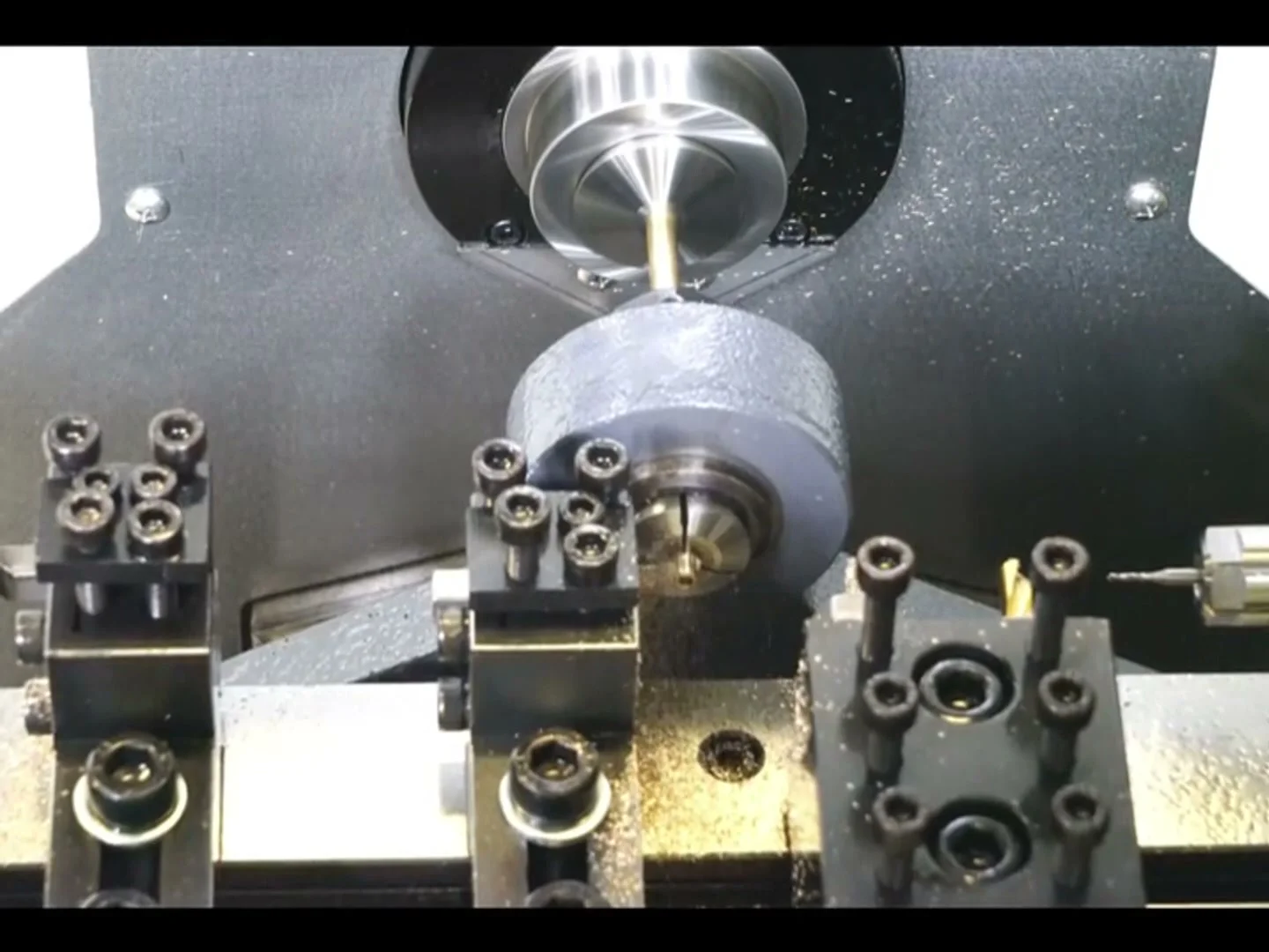
A fixed guide bush holds the bar without rotating with it. Its basic advantage is a direct, constrained relationship between the bar and the guide surface. For a short supported length, that can provide a clean and repeatable reference, provided the bar, guide clearance, lubrication, and setup are well controlled.
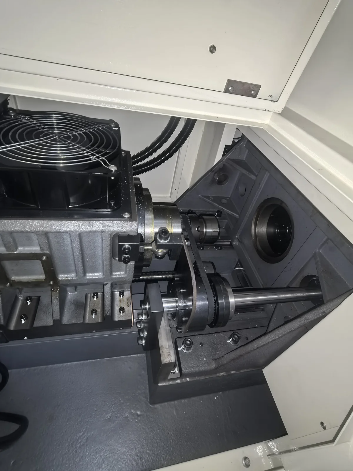
A rotating guide bush turns with the bar. That removes the relative sliding motion at the guide interface. The benefit is not simply “more speed.” It is the reduction of rubbing over the length of bar that passes through the guide. Less relative motion can reduce frictional heating and the tendency to mark or pull the material surface during a long turning pass.
This creates the apparent contradiction that often confuses buyers. A job can have a tight tolerance and still need a rotating guide bush. The tolerance remains important, but it is no longer the only variable controlling the result. If the turning length is long enough, the fixed bush may introduce a thermal and friction problem that outweighs its static positioning advantage.
The practical question is not:
“Which guide bush is inherently more accurate?”
It is:
“Which guide bush keeps the bar, guide interface, and cutting condition stable for this tolerance over this turning length?”
That question also explains why a recommendation should be validated with the actual bar and workpiece. A guide bush that looks appropriate from a tolerance chart may behave differently when the material is not perfectly straight, when the bar surface varies, or when the process turns from both ends.
How turning length changes the decision
Friction and heat accumulate with contact length
With a fixed guide bush, the rotating bar slides against the guide surface. The contact condition depends on lubrication, clearance, bar diameter, surface condition, and alignment. Over a short length, the resulting heat and drag may remain small enough to manage. Over a long turning length, the same interface has more opportunity to generate heat and resistance.
Deflection itself scales sharply with unsupported length — doubling the distance from the support to the cutting force multiplies deflection roughly eightfold — so a support condition that is comfortable over a short turn is not comfortable over a long one. Thermal growth does not need to be dramatic to affect a close tolerance. A small change in the bar, guide bush, or machine condition can shift the cutting relationship while the operation is still running. The risk is higher when the job requires repeatability over many pieces rather than a single successful test cut.
Bar straightness becomes part of the guide bush problem
A long slender bar is not only a material feedstock. It is also a moving reference. Any bow, surface variation, or inconsistent stock condition changes how the bar contacts the guide bush; centerless-ground stock is specified precisely to control diameter and roundness for this reason, and worn or mismatched bushings are a documented source of dimensional-control trouble on Swiss-type machines. As the unsupported or newly exposed length changes, the cutting force and guidance condition can change with it.
A rotating guide bush does not make an inaccurate bar straight, and it does not remove the need for correct adjustment. Its value is that the bar and guide interface rotate together, reducing the relative sliding that would otherwise amplify the long-travel problem.
Two-end turning increases the need for a complete stability check
When a part is turned from both ends, the process must maintain a reliable relationship through more than one cutting direction or workholding condition. The guide bush selection cannot be separated from the sequence, the amount of material left for the second end, and how the part is transferred or supported. For a deeper look at the complete turning sequence and workholding strategy on Swiss-type lathes, see the general process overview.
The phrase “two-end turning” should therefore trigger a process review. Confirm which operations occur while the bar is supported by the guide bush, which dimensions are generated from each end, and whether the second operation can reveal taper, runout, or surface marks that were not obvious in a one-end test.
Length-to-diameter ratio is a useful screening signal
Absolute length is easy to communicate, but length-to-diameter ratio often explains the mechanics better; conventional turning practice already reaches for added support past roughly 3:1 and a steady rest past 6:1. A 200 mm turning length is a very different guidance problem at 5 mm diameter than at 18 mm diameter. Use L/D as a screening value, then confirm the decision with the actual stock, tool forces, and tolerance.
L/D is not a universal pass/fail threshold. It is a way to prevent a short tolerance statement from hiding a long, flexible, heat-sensitive turning condition. When L/D is high, give more weight to friction, thermal stability, bar straightness, support location, and surface protection.
A two-dimensional guide bush selection table
The table below is a process-screening tool, not a substitute for a machine trial. “Short,” “medium,” and “long” refer to the supported turning condition and should be interpreted with L/D, bar quality, material, and cutting forces. The important point is that the recommendation changes when length changes, even if the tolerance stays the same.
| Required tolerance | Short turning length / low L/D | Medium turning length / moderate L/D | Long turning length / high L/D | Main check |
|---|---|---|---|---|
| General tolerance, low surface sensitivity | Fixed guide bush is often suitable | Compare friction, heat, and bar condition | Rotating guide bush may reduce rubbing risk | Stability over a production run |
| Moderate tolerance, surface must remain clean | Fixed guide bush if clearance and lubrication are stable | Trial both options against surface marks and drift | Rotating guide bush is often the safer starting point | Surface condition and thermal drift |
| Tight tolerance, short supported turn | Fixed guide bush can provide a direct reference | Validate with bar straightness and guide adjustment | Do not choose by tolerance alone; assess L/D and heat | Repeatability, not one-piece accuracy |
| Tight tolerance, long turn or high L/D | Fixed only after a controlled trial | Rotating guide bush becomes increasingly attractive | Rotating guide bush is the recommended starting point | Friction, heat, runout, and two-end sequence |
| Tight tolerance plus two-end turning | Review transfer and support before selecting | Confirm the second-end datum and bar exposure | Rotating guide bush may be required when long travel is involved | Full sequence capability |
For the case behind this article, the relevant row is the last two rows: the turning length is approximately 200 mm, the stated tolerance is 0.02 mm, and the requirement includes turning from both ends. That combination is why the recommendation was to add a rotating guide bush even though common summary advice would point toward a fixed bush for precision.
Applying the rule to a 200 mm two-end turning job
The source process began with smaller work made on a cam-type automatic lathe. The reported problem was not a validated precision process: manual adjustment was heavy and the result was described as lacking precision. The replacement direction used a three-axis sliding-headstock (Swiss-type) lathe with four driven tool positions and an automatic bar feeder. The baseline machine arrangement was supplied with a fixed guide bush.
The initial workpiece was an EN8D part approximately 8 mm in diameter and 138 mm long. The part included four grooves, chamfers, an undercut, and a thread blank. The groove information included a 1.05–1.15 mm groove with a 6.8–7.00 mm diameter, a 3–3.5 mm groove with a 7.5 ±0.05 mm diameter, and a 5.25–5.30 mm thread blank diameter. These details matter because the guide bush decision sits inside a real cutting sequence, not in a generic machine comparison.
The later requirement added 12.75 mm and 17.05 mm diameters and specified turning from both ends. The stated turning length was approximately 200 mm with a 0.02 mm tolerance. At that point, the problem definition changed. The process was no longer only “hold a small diameter accurately.” It became “hold a close dimension while the bar travels through a long turning condition and the part is addressed from both ends.”
That is the point at which a rotating guide bush became the recommended change. The change does not claim that a rotating bush is universally more accurate. It recognizes that long relative sliding can become the limiting mechanism. By allowing the guide bush to rotate with the bar, the setup removes one major source of rubbing during the long travel. The remaining risks then move toward alignment, concentricity, adjustment, bearing condition, and the quality of the incoming bar.
The correct acceptance test should compare the two arrangements under the same material and cutting conditions. Measure the first-piece result, warm-up drift, dimensional spread over a representative run, surface marks, and the relationship between the first and second ends. A single part that meets 0.02 mm does not prove that the selected arrangement is stable in production.
flowchart LR
    A[Tolerance and turning length] --> B{Long turn or high L/D?}
    B -->|No| C[Start with fixed guide bush]
    B -->|Yes| D[Start with rotating guide bush]
    C --> E[Trial under production conditions]
    D --> E
    E --> F[Measure drift, surface, runout]
    F --> G[Select on stability, not the label]
What to verify before changing the setup
Confirm the actual bar and guide-bush envelope
The machine boundary in the source project covered product diameters from approximately 5 to 18 mm and product lengths from approximately 80 to 1000 mm. The incoming material included 8.05 mm, 12.75 mm, and 17.05 mm stock in 1000 mm lengths. These are useful project facts, but they are not a universal specification for every sliding-headstock lathe.
Before ordering or fitting a guide bush, confirm the actual bar diameter, guide-bush bore range, required clearance, stock surface, straightness, and the machine's compatible rotating-bush arrangement. If 20 mm stock is used on a machine limited to an 18 mm processing range, the source process required the tail of the bar to be pre-turned to 18 mm for approximately 20 mm. That is a material-preparation constraint, not a reason to assume that every 20 mm bar can be fed directly.
Separate guide-bush issues from downstream operations
The source sequence also included facing or burr removal, grinding, thread rolling or knurling, and milling. The guide bush is selected for the turning and guidance condition, but the final process must still protect the surfaces and datums needed by those later operations. A guide bush that improves long-turn stability but marks a functional surface is not a successful solution.
The end-face hexagon was also identified as an operation that the referenced three-axis sliding-headstock arrangement could not complete and that required a press operation. This is a useful reminder to keep the guide-bush decision in its proper scope: it can solve a guidance problem, but it cannot make an unavailable downstream operation appear on the machine.
Check adjustment and concentricity sensitivity
A rotating guide bush removes relative rotation at the guide interface, but it makes setup quality important. Check the bush alignment to the spindle and the cutting axis, the bearing condition, the fit around the incoming bar, and the repeatability of the adjustment. Confirm that the bar enters without excessive drag and that the bush is not masking a feed, collet, or spindle-alignment issue.
For two-end turning, establish which datum controls each end and how the part is supported during the second operation. Measure coaxiality or runout where the drawing requires it. Do not use a generic statement that “rotating is for long parts” as the acceptance criterion.
Run a controlled comparison
A useful trial records the same evidence for fixed and rotating arrangements:
- Use the same EN8D stock condition and the same nominal diameter.
- Record guide-bush adjustment, lubrication condition, cutting tools, speeds, feeds, and coolant state.
- Measure the critical dimension at warm-up and at intervals during the run.
- Inspect the turned surface for scoring, pickup, or rubbing marks.
- Check both ends and record runout or alignment results.
- Repeat enough pieces to expose drift rather than accepting a single first-off part.
This comparison turns guide bush selection from a catalog preference into a measured process decision. It also gives the machine builder and production team a shared basis for deciding whether the rotating arrangement is necessary, beneficial, or unnecessary for a particular part family.
FAQ
Is a fixed guide bush always more accurate than a rotating guide bush?
No. A fixed guide bush can provide a strong reference for short, well-controlled turning, but accuracy in production depends on the complete process. For long turning, friction, heat, bar straightness, and surface damage can dominate. A rotating guide bush may produce the more stable result when it removes relative sliding over a long travel.
When should a Swiss type lathe use a rotating guide bush?
Start by considering a rotating guide bush when the turning length is long relative to the bar diameter, when the process turns from both ends, or when fixed-bush rubbing produces heat, scoring, or dimensional drift. A close tolerance such as 0.02 mm strengthens the case for a controlled comparison, but tolerance alone should not decide the selection.
What is the most important guide bush selection input?
The most important input is the complete turning condition: required tolerance together with turning length or L/D, bar diameter and quality, material, surface requirement, cutting forces, and the number of turning ends. Treating guide bush selection as a tolerance-only decision can miss a long-travel friction and thermal problem.
Can a rotating guide bush correct a bent bar?
No. It reduces relative sliding between the bar and the guide interface, but it cannot straighten poor stock or correct machine misalignment. Check incoming bar straightness, diameter consistency, surface quality, spindle and guide alignment, and the adjustment procedure before attributing variation to the guide bush type.
Choose the guide bush from the whole process
The practical answer to rotating vs fixed guide bush is conditional. Fixed guide bushes remain appropriate for many short, controlled turning conditions. Rotating guide bushes become the better starting point when long turning length, high L/D, two-end turning, and close tolerance combine to make friction and heat the likely limiting factors.
For the documented process point, approximately 200 mm of turning with a 0.02 mm tolerance and turning from both ends justified adding a rotating guide bush. The lesson is not to replace every fixed bush. It is to stop treating tolerance as the only axis of the decision.
If you are selecting guidance for a new sliding-headstock process, compare the guide bush options against the actual bar, turning length, surface requirement, and complete operation sequence. Contact UBright Solutions to discuss the machine envelope, bar preparation, and a measured guide-bush trial for your part family.
Published 2026-08-21. Last reviewed 2026-08-21.
References
- Switching to Swiss Without a Guide Bushing — Production Machining, 25 February 2010. Trade-press background on when a guide bushing is and is not required on sliding-headstock lathes, including the length-to-diameter screening range and the bar-stock preparation it implies.
- Deflection and Precision in Swiss Metal CNC Machining — Metal Cutting Corporation, 13 June 2020, updated 25 August 2023. Quantifies how deflection grows with unsupported length and gives the conventional 3:1 and 6:1 length-to-diameter support thresholds.
- Guide Bushings for Swiss Lathes: Everything You Need to Know — Absolute Machine Tools. States the common tolerance-based split between rotary and fixed bushings, and the surface-marring behaviour of fixed bushings that the long-turn case in this article runs into.
- Swiss Made: Drilling Performance — Cutting Tool Engineering, Glen Crews and Bill Kennedy, 15 April 2011. Trade-press treatment of guide bushing condition as a dimensional-control factor, and the centerless-ground bar specification Swiss work depends on.
- How It Works – Centerless Grinding — Today's Machining World, 18 February 2006, updated 23 May 2022. Documents the diameter and roundness tolerances centerless grinding holds, and why bar straightness affects chatter and bushing seizure.