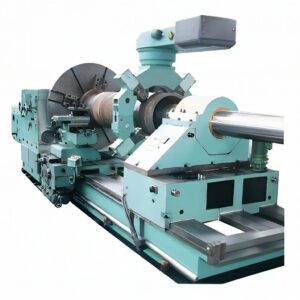
- Horizontal Orientation
- The most prominent feature is its horizontal layout. The broaching tool and the workpiece are arranged horizontally. This design allows for a stable machining process as the force exerted during broaching is distributed in a more balanced way along the horizontal axis. For example, when broaching a keyway on a long shaft, the horizontal position helps to ensure that the shaft remains in a stable position and the broaching tool can move smoothly through the workpiece.
- High – Precision Machining
- Horizontal broaching machines are known for their high – precision capabilities. The broaching process is a continuous cutting operation that can achieve very accurate dimensions. The tool’s teeth are precisely shaped and spaced to remove material in a controlled manner. It can achieve tight tolerances, usually in the range of a few micrometers. This makes it suitable for manufacturing components such as gears and splines, where dimensional accuracy is crucial. The accuracy of the machine is maintained through a rigid construction and precise guiding systems that keep the broaching tool on the correct path.
- High – Efficiency Material Removal
- They have a high material – removal rate. The broaching tool has multiple cutting teeth, and as it moves relative to the workpiece, each tooth successively removes a layer of material. This multi – tooth cutting action allows for a large amount of material to be removed in a single pass. Compared to other machining methods like milling or turning, broaching can often complete the machining of a complex shape much more quickly. For instance, in the production of internal splines in a hub, a broaching machine can quickly shape the splines to the desired form with a high rate of material removal.
- Specialized Broaching Tools
- The machine uses specialized broaching tools. These tools are designed according to the specific shape of the workpiece to be machined. For example, if the workpiece requires a complex internal profile such as a non – circular hole or a profiled groove, the broaching tool will have a corresponding shape. The tools are usually long and slender to fit into the workpiece and perform the broaching operation. They are made of high – quality tool steels and are often coated to improve wear resistance and cutting performance.
- Rigid Machine Structure
- A horizontal broaching machine has a very rigid structure. The bed of the machine is usually made of high – quality cast iron to provide a stable base. The columns and guideways that support the broaching tool and the workpiece – holding fixtures are also designed to be rigid to withstand the cutting forces. This rigidity is essential to prevent vibrations during the machining process. Vibrations can lead to poor surface finish and inaccurate machining dimensions. The rigid structure ensures that the broaching tool and workpiece maintain their relative positions accurately during the cutting process.
- Suitable for Mass Production
- Horizontal broaching machines are well – suited for mass production. Once the broaching tool is set up and the machine is calibrated for a particular workpiece, it can produce a large number of identical components with high precision and efficiency. The quick material – removal process and the ability to maintain consistent quality make it a preferred choice for industries such as automotive and aerospace, where a large number of parts with the same specifications need to be manufactured. For example, in the production of engine components like valve guides, a horizontal broaching machine can produce thousands of parts with the same dimensions and surface quality.
S/N | Main technical parameters | Unit | L6120 | L6140 | L6160 |
1 | Rated broaching force | kN | 200 | 400 | 600 |
2 | Rated stroke of slide | mm | 1600 | 2000 | 2000 |
3 | Working stroke speed (stepless) | m/min | 1~10 | 1.5~7 | 2~7.5 |
4 | Backstroke speed (stepless) | m/min | 2~20 | 3~18 | 3~18 |
5 | Size of end plate surface | mm | 640×620 | 640×640 | 640×550 |
6 | Hole diameter of end plate | mm | Φ200H7 | Φ250H7 | Φ250H7 |
7 | Faceplate hole diameter | mm | Φ130H7 | Φ150H7 | Φ150H7 |
8 | Height from positioning surface to floor (operating height) | mm | 850 | 850 | 850 |
9 | Axial plunger pump for main drive | A145-F-R-04 | A3H180-FR14K | A3H320-FR14K | |
Displacement | mL/r | 145 | 180 | 320 | |
Max. operating pressure | MPa | 16 | 16 | 16 | |
Rated operating pressure | MPa | 12 | 11 | 11 | |
10 | Main drive motor | YE3-200L-4 | Y200L-4-B35 | Y225M-4-B55 | |
Power | kW | 33 | 45 | 55 | |
Rotate speed | rpm | 1470 | 1470 | 1470 | |
11 | Auxiliary pump – variable vane pump | SVPF-40-70 | SVPF-40-70 | SVPF-40-70 | |
Displacement | mL/r | 22.2 | 22.2 | 22.2 | |
Max. operating pressure | MPa | 6 | 6 | 6 | |
Rated operating pressure | MPa | 4 | 4 | 4 | |
12 | Electric motor for auxiliary pump | ||||
Power | kW | 2.2 | 2.2 | 2.2 | |
Rotate speed | rpm | 1470 | 1470 | 1470 | |
13 | Cooling pump | DB-100 | DB-100 | DB-100型 | |
Flow | L/min | 100 | 100 | 100 | |
14 | Motor power of cooling pump | kW | 0.25 | 0.25 | 0.25 |
Motor speed of cooling pump | rpm | 3000 | 3000 | 3000 | |
15 | Total motor capacity | kW | 33 | 33 | 48 |
16 | Working space of machine tool (L×W×H) | mm | 7250×2400×1300 | 8640×2500×1480 | 8700×2800×1480 |
17 | Machine weight | kg | 8000 | 12000 | 16000 |
S/N | Item | Brand | Remarks | ||
I. Mechanical Part | |||||
1 | Machine body | Standard | Own made | √ | |
2 | Main slide | Standard | Own made | √ | |
3 | Big faceplate | Standard | Own made | √ | |
4 | Main oil cylinder (effective stroke L = 2000mm) | Standard | Own made | √ | |
5 | Broach holder | Standard | Own made | √ | |
6 | Tailstock | Standard | Own made | √ | |
II. Hydraulic Part | |||||
7 | Mainly hydraulic system (hydraulic schematic diagram) | Standard | Own made | √ | |
8 | Variable displacement axial piston pump | Standard | YUKEN, Japan | √ | |
9 | Hydraulic station (oil tank assembly drawing) | Standard | Own made | √ | |
III. Electrical Part | |||||
10 | PLC | Standard | Siemens | √ | |
11 | Contactor, relay | Standard | Siemens | √ | |
12 | Electrical control cabinet | Standard | Own made | √ | |
13 | Proximity Switch | Standard | Switzerland Contrinex | √ | |
IV. Other Parts | |||||
14 | Cooling pump (DB-100A) | Standard | √ | ||
15 | Automatic chip removal (magnetic or scraper type) | Standard | Shandong Yufeng | √ | |
V. Special Accessories | |||||
16 | Main and auxiliary broach (handle diameter D= mm) | One set of standard configuration | Own made | √ | |
17 | Broach | Optional | |||
18 | Adjusting pad iron (1 set) | Standard | Own made | √ | |
19 | One set of vulnerable sealing part | Standard | √ | ||