
An inverted vertical lathe can improve brake disc machining by combining automated part pickup, two-sided turning, stable clamping, high-speed CBN tooling, and in-process measurement in one controlled cell. For brake disc manufacturers, the main value is not only faster cutting. It is the reduction of manual handling, reclamping variation, and process instability around the disc’s critical friction faces.
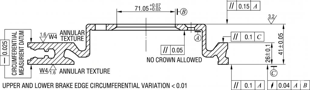
Brake disc machining is the turning, drilling, chamfering, finishing, and inspection work used to bring a cast or semi-finished brake disc to its final functional geometry. The process must control friction-surface finish, thickness variation, lateral runout, and repeatability because brake rotors are safety-related parts and geometric variation can contribute to vibration, judder, or uneven braking behavior. SAE’s J3111 recommended practice focuses specifically on brake rotor thickness variation and lateral run-out measurements, which shows why these dimensions matter in rotor evaluation and process control.
Brake Disc Machining Requirements That Drive the Process Choice
A brake disc is simple in outline but demanding in production. The two friction faces must be machined consistently because they are the surfaces that contact the brake pads. If the machining process leaves unstable thickness, uneven surface texture, or excessive runout, the result can be noise, vibration, pedal pulsation, or reduced comfort in service.
For manufacturers, this creates three practical requirements. First, the machining process needs stable clamping so that each face is cut from a repeatable datum. Second, the line must protect machined surfaces from dents and handling marks. Third, the process needs enough measurement feedback to detect drift before it becomes a batch quality problem.
The source case describes a conventional vertical turning process with low automation, manual clamping, two handling steps, and weak process capability for surface roughness and DTV control. That does not mean every conventional process fails. It means that, for high-volume brake disc production, the part geometry and quality targets put pressure on the whole system: machine structure, fixture strategy, cutting tool, transfer method, and inspection loop.
From Conventional Vertical Turning to Automated CNC Vertical Lathe Machining
Conventional vertical turning can machine disc-shaped parts, but it often depends on manual loading, manual unloading, and separate setups for opposite faces. In the source process, the part needed secondary clamping, operators handled the workpiece directly, and the cutting line speed was below 500 m/min. Those factors affected both throughput and quality stability.
Automated CNC vertical lathe machining changes the process layout. Instead of treating each machine as an isolated operation, the line combines conveyors, automated loading, rough turning, finishing, drilling, and measurement into a linked cell. The workpiece moves through the process with less manual contact, and the control system coordinates spindle, turret, and transfer movements.
In practical lathe machining terms, the difference is a shift from operator-centered handling to machine-centered flow. The automated cell described in the source uses two machines: one mainly for roughing and one for finishing and drilling. A conveyor and handling system feed blanks to the first machine, then transfer semi-finished parts to the second machine for later operations.
For buyers comparing a CNC vertical lathe for brake disc machining with a simpler standalone turning setup, the key question is not only spindle power or maximum turning diameter. It is whether the cell can reduce manual transfer, keep both braking faces under control, and close the loop between machining and measurement.
Why an Inverted Vertical Lathe Fits Brake Disc Machining
An inverted vertical lathe uses an inverted spindle that can move down to pick up a workpiece, clamp it, move it into the cutting position, and transfer it to another station. In the brake disc application described by the source, the machine is paired with an upright spindle. The upright and inverted arrangement lets the part move between machining positions without a separate manual flip.
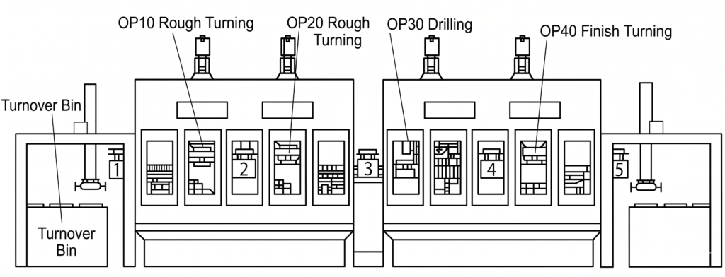
The upright spindle works like a more familiar vertical turning station, while the inverted spindle adds automated pickup and transfer capability. This is especially useful for brake discs because both sides of the part matter. A layout that reduces reclamping and manual handling reduces two common sources of variation: datum changes and surface damage.
Stage 1 — Loading the blank
Brake disc blankConveyor loadingInverted spindle pickup
flowchart LR
    A[Brake disc blank] --> B[Conveyor loading] --> C[Inverted spindle pickup]
Once the inverted spindle has clamped the blank, the part moves into Machine 1 for two-sided roughing.
Stage 2 — Roughing on Machine 1
Rough turn first sideTransfer to upright spindleRough or finish second side
flowchart LR
    D[Rough turn first side] --> E[Transfer to upright spindle] --> F[Rough or finish second side]
After roughing, a transfer mechanism moves the semi-finished part from Machine 1 to Machine 2 for the finishing and inspection stage.
Stage 3 — Finishing, measurement, and unload on Machine 2
Drilling and chamferingFinal finishingIn-process measurement and data feedbackUnload finished part
flowchart LR
    G[Drilling and chamfering] --> H[Final finishing] --> I[In-process measurement and data feedback] --> J[Unload finished part]
The source process uses this principle across two machines. The blank is loaded to a conveyor, moved under the inverted spindle of the first machine, clamped by the chuck, and rough turned. The inverted spindle then transfers the workpiece to the upright spindle for machining the other side. After roughing, a transfer mechanism moves the part to the second machine for drilling and finishing operations.
This upright-and-inverted structure is the main reason the layout fits automated brake disc production. It turns the spindle into both a machining element and a handling element, reducing the number of times people or external devices need to touch the part.
Accuracy Controls: Rigidity, Servo Positioning, CBN Tools, and In-Process Measurement
Accuracy in brake disc production does not come from one feature alone. It comes from the combined effect of machine rigidity, repeatable axis control, stable clamping, proper tooling, and measurement feedback.
The source machine uses an H-shaped structure to improve rigidity between the base, spindle, turret, and moving units. Rigidity matters because vibration and deflection can affect friction-surface finish and dimensional repeatability. The source also describes closed-loop control on both rotary and linear axes: angular repeatability below ±5″, and X/Z-axis repeatability below ±0.005 mm.
Tooling also changes the process window. The source case uses CBN cutting tools at cutting speeds up to 1200 m/min, compared with the lower speed of the earlier process. CBN tooling is especially useful when the application requires both productivity and stable finishing behavior, but the exact cutting parameters still depend on disc material, insert grade, machine stiffness, coolant strategy, and finishing allowance.
Measurement closes the loop. In the finishing machine described by the source, an active measuring system records key dimensions after machining and feeds the data back to the system. The reported process capability for critical dimensions is CPK > 1.67 in that implementation. That figure should be read as a case result, not a universal guarantee; it depends on the full line configuration and process discipline.
External rotor literature supports the same direction. A technical study on gray cast iron brake rotors describes brake discs as critical vehicle components and discusses geometric tolerances including DTV, lateral runout, minimum thickness, and surface roughness. Those are exactly the types of outcomes a controlled turning and measurement process is designed to stabilize.
Productivity and Quality Gains from Automated Brake Disc Machining
The source case reports several measurable gains from switching to the upright/inverted automated layout. Single-shift operators were reduced from 2 to 1. Process equipment was reduced from 5 machines to 2. Cycle time dropped from 112 seconds to 49 seconds. First-pass yield increased from 95.8% to about 99.65%. JPMH, or per-person hourly labor productivity, improved by nearly 2.5 times.
These figures are useful because they show where automated brake disc machining creates value. Labor reduction comes from automated loading, transfer, and unloading. Equipment reduction comes from combining turning, drilling, chamfering, finishing, and measurement into fewer stations. Cycle-time reduction comes from faster transfer and higher-speed cutting. Yield improvement comes from reduced handling damage and better control of critical surfaces.
For production managers, the most important lesson is that the gains are system-level. Buying a faster lathe alone does not automatically reproduce the result. The line must be planned around part flow, datum control, tool life, measurement strategy, chip management, operator access, and maintenance. The machine layout is the foundation, but the full process determines the output.
Where the Process Fits in a Brake Disc Manufacturing Process
A brake disc manufacturing process usually includes steps outside the lathe cell, such as casting or forging, heat treatment where required, rough machining, finish machining, drilling, balancing, coating, cleaning, and final inspection. The upright/inverted vertical lathe cell mainly belongs to the turning, drilling/chamfering, finishing, and measurement portion of that chain.
That positioning matters when evaluating equipment. The cell does not replace every upstream or downstream operation. Instead, it strengthens the machining stage where the friction faces, mounting features, and related surfaces are brought into controlled geometry. If coating or surface treatment follows machining, the lathe process still needs to deliver consistent geometry and a surface condition suitable for later operations.
The upright/inverted vertical lathe cell mainly belongs to the turning, drilling/chamfering, finishing, and measurement portion of that chain.
When Should Manufacturers Consider This Lathe Machining Layout?
Manufacturers should consider an upright/inverted vertical turning layout when brake disc production volume is high enough to justify automation and when both sides of the part contain quality-critical surfaces. The layout is also attractive when manual handling damage, inconsistent reclamping, or weak measurement feedback are already limiting yield.
A good fit usually includes at least one of these conditions: high-volume disc production, strict friction-face requirements, frequent two-sided machining, a need for integrated drilling or chamfering, or a plant strategy built around automated cells rather than standalone machines.
The layout is not automatically the best choice for every shop. Low-volume prototyping, simple repair work, or parts without critical two-sided surfaces may not justify the automation cost. In those cases, a conventional vertical turning lathe or simpler fixture strategy may be enough. The decision should compare not only machine price, but also cycle time, labor, scrap, floor space, measurement requirements, and the cost of quality variation.
FAQ
How does an inverted vertical lathe machine brake discs?
An inverted vertical lathe machines brake discs by using a downward-facing spindle to pick up the blank, clamp it, move it into the cutting area, and transfer it between machining positions. In an automated cell, this allows roughing, second-side machining, finishing, drilling, and measurement to happen with fewer manual handling steps.
Why use an inverted spindle for brake disc machining?
Use an inverted spindle when the production goal is to reduce reclamping, automate transfer, and protect machined surfaces from manual handling damage. The inverted spindle is most valuable when both sides of the brake disc require controlled machining and the line needs repeatable flow rather than operator-dependent part movement.
What improves brake disc machining accuracy most: the machine, tooling, or measurement?
Brake disc machining accuracy usually improves most when the machine, tooling, clamping, and measurement system are engineered together. A rigid machine without measurement can still drift, a good measuring system cannot fix unstable cutting, and premium tooling will underperform if the part is not clamped from a repeatable datum.
Is an upright vs inverted vertical lathe layout only useful for brake disc production?
No. The same concept can apply to other disc-shaped or short cylindrical parts that need automated loading, stable two-sided machining, and reduced handling. Brake discs are a strong example because the two friction faces and thickness-related dimensions make reclamping and transfer control especially important.
Conclusion
An inverted vertical lathe is valuable for brake disc machining because it connects machining accuracy with automated process flow. The source case shows that an upright/inverted vertical lathe cell can reduce handling, combine operations, support higher cutting speeds, add in-process measurement, and improve both productivity and first-pass quality.
For manufacturers evaluating vertical lathe machining equipment, the best question is not simply whether the machine can turn a brake disc. The stronger question is whether the complete cell can control both braking faces, reduce manual variation, measure critical dimensions, and deliver the cycle time required by the production line.
UBright Solutions can help manufacturers evaluate CNC vertical lathe layouts, process flow, and automation options for brake disc and disc-shaped component machining. To discuss a production requirement, contact UBright Solutions at info@ubrightsolutions.com.
References
- SAE J3111_202412: Brake Rotor Thickness Variation and Lateral Run-Out Measurements — SAE International, 2024; supports the relevance of brake rotor thickness variation and lateral run-out measurement.
- Effects of stress-relief and natural aging on geometric tolerances of gray cast iron brake rotors — Springer Nature, 2024; supports the discussion of brake discs as critical components and the importance of DTV, lateral runout, thickness, and surface roughness.