
In modern automotive and aerospace manufacturing, the dimensional accuracy of rotating components directly impacts transmission stability, noise levels, and overall operational lifespan. When dealing with high-strength chrome-molybdenum alloy steel components, mitigating heat treatment distortion is a critical manufacturing hurdle. To address these industry-wide challenges, U•Bright Solutions provides world-class Straightening Solutions designed specifically for the rigorous demands of Gear Shaft production.

By leveraging advanced servo-control technologies and intelligent meshing measurements, our systems reliably correct Pitch Circle Diameter (PCD) runout, keeping final tolerances strictly within 0.02mm. This article explores how upgrading to a fully automated shaft straightening system can transform your quality assurance process and eliminate production bottlenecks.
The Challenge: Controlling Gear Shaft PCD Runout
Complex Material & Tolerance Requirements
A recent project required tailored PCD runout correction for a series of multi-start helical gear shafts (e.g., Part Nos. GR242-BT9-00, GR242-ZY9-00) ranging from 16.2mm to 20mm in diameter and up to 253mm in length. Manufactured from robust Cr-Mo alloy steel, these components are highly susceptible to micro-bending during preceding machining or carburizing stages.
The client’s technical specifications mandated a final PCD runout accuracy of under 0.02mm. However, the initial Total Indicator Reading (TIR) before straightening was routinely three to four times higher than the target value. Straightening such high-hardness materials within micrometer-level tolerances is exceptionally difficult. Furthermore, to guarantee accurate positioning during the cycle, the workpieces must feature pristine center holes and distinct drive ends.
Advanced Automated Shaft Straightening System Features
To resolve these complexities, we engineered a state-of-the-art automated shaft straightening system. Operating on a highly rigid gantry frame, this straightening machine relies on single-point servo control to apply precise loads, ensuring parts are never over-bent or fractured.
Master Gear Integration for Precise Measurement
Standard optical or contact probes measuring the outer diameter cannot accurately reflect the true operational runout of a helical gear. Meeting the rigorous standards outlined by the American Gear Manufacturers Association (AGMA) for gear meshing and inspection, our system utilizes high-precision master gears as the measurement baseline.
During the automated measurement phase, the servo drive rotates the gear shaft while the master gear meshes perfectly with it. The machine captures the exact radial displacement, calculating the true PCD runout and analyzing the pitch circle’s ovality error with a remarkable measurement resolution of 0.001mm.
High-Speed Straightening Process & Servo Control
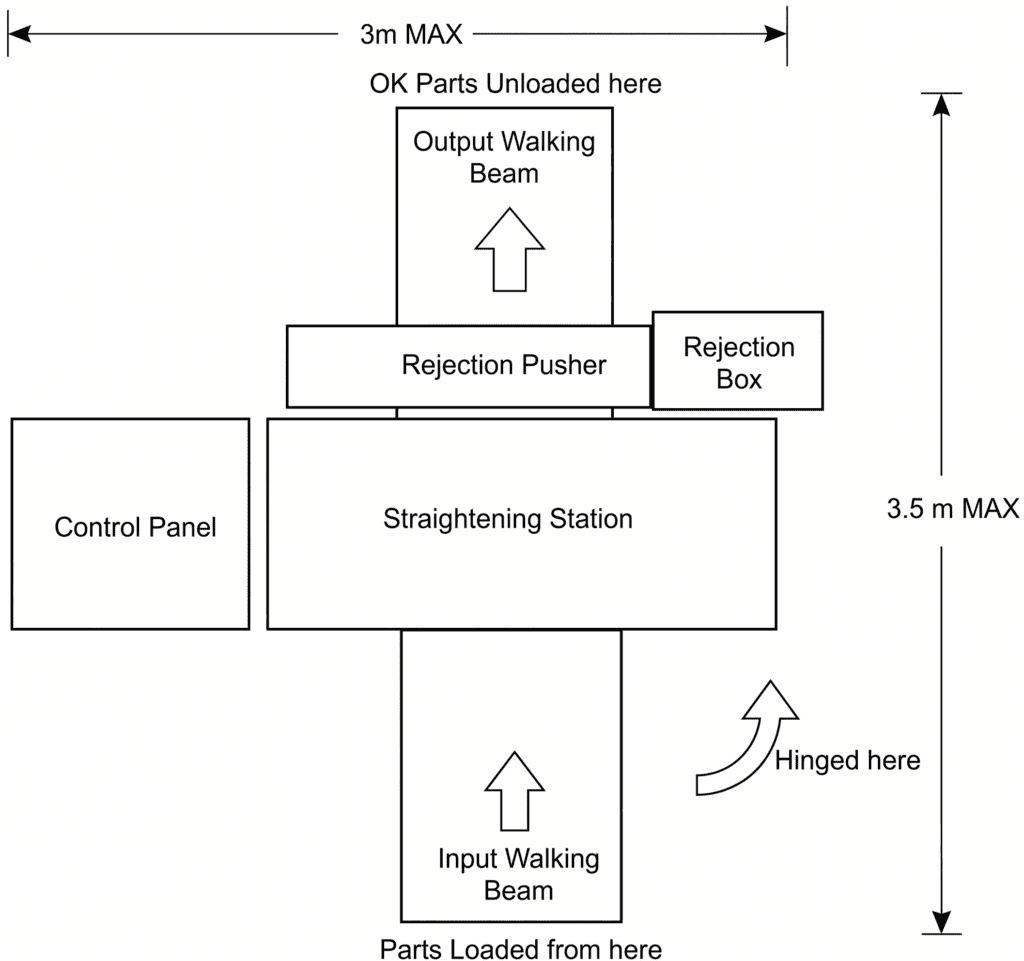
Designed for high-volume production, the equipment executes a high-speed straightening process. It features an automated walking-beam loading/unloading mechanism capable of staging 6 raw parts and 6 finished parts.
Before the straightening cycle begins, an integrated cleaning device automatically clears iron filings and debris from the workpiece’s center holes, ensuring flawless datum alignment. With a maximum load capacity of 100 kN and X-axis travel speeds up to 400 mm/s, the machine achieves an average cycle time of ≤ 25 seconds per part (excluding loading/unloading), drastically boosting overall plant throughput.
Built-in AE Crack Detection Technology
Applying immense pressure to alloy steel poses the risk of micro-cracking. Aligned with non-destructive testing principles endorsed by the American Society for Nondestructive Testing (ASNT), our machine incorporates a sophisticated Japanese AE-5 Acoustic Emission crack detection system.
If the AE sensor detects the high-frequency acoustic waves associated with micro-fracturing during the pressing phase, the system instantly halts the load. The defective workpiece is then automatically segregated by a rejection pusher into a designated rejection box (3-part capacity), guaranteeing that zero cracked components advance to the next manufacturing stage.

Straightening Process Workflow & Software Intelligence
The true core of this equipment is its proprietary, professional-grade straightening control software. Running on a localized Windows 10 industrial touch-panel PC, the interface provides beautiful, highly intuitive digital and European-style bar graph displays for dynamic process observation.
Multi-Level Security & Intelligent Features
To ensure operational safety and process control, the software utilizes a strict 4-level permission architecture:
- Lv1 Operator: Basic operation and equipment start/stop.
- Lv2 Setup/Adjuster: Fixture calibration and minor parameter adjustments.
- Lv3 Administrator: Core tolerance modification and production planning.
- Lv4 Manufacturer: Deep algorithm access and underlying hardware diagnostics.


Operators can easily execute changeovers using visual part diagrams and fixture rulers displayed on the screen. By simply calling up a part number, the system instantly loads the corresponding parameters from a massive database capable of storing over 100 distinct workpiece profiles.
Self-Learning Algorithms & SPC Data Tracking
The software features profound self-learning capabilities. By “teaching” the machine with a single part, it establishes baseline straightening parameters. As production continues, it statistically processes historical data to automatically build the optimal straightening curve. It analyzes the specific bending amount and instantly applies the exact stroke needed for rapid correction.
Furthermore, all straightening data is automatically stored in a highly stable SQLite database. Utilizing an industrial Ethernet interface, the machine seamlessly links with factory MES (Manufacturing Execution Systems) and SPC (Statistical Process Control) networks. It dynamically pushes equipment alarms, real-time production counts, and pre- vs. post-correction TIR runout analytics, fully enabling Industry 4.0 data traceability.
Machine Specifications & Plant Layout
Below are the primary technical parameters of the servo-controlled gear shaft straightening machine:
| Parameter | Value |
| Frame Type | Gantry |
| Max. Load Capacity | 100 kN |
| Shaft Diameter / Length | Ø10~Ø25 mm / 120~500 mm |
| Measurement Resolution | 0.001 mm |
| Target Straightening Accuracy | ≤ 0.02 mm (PCD) / ≤ 0.05 mm (Overall) |
| Average Cycle Time | ≤ 25s/pc |
| X-Axis / Y-Axis Speed | 90~400 mm/s / 30~90 mm/s |
| Power Supply | AC 380V±10%, 50Hz, 3P5W, 18 kW |
Consult U•Bright Solutions for Custom Equipment
U•Bright Solutions is a premier equipment provider specializing in advanced deformation control, automated precision measuring, and turnkey mechanical manufacturing. If you are struggling with out-of-tolerance gear components or looking to automate your quality control processes, our expert engineering team is ready to assist.
- Email us for a technical consultation: info@ubrightsolutions.com
- Visit our website to learn more: https://www.ubrightsolutions.com/
Verification List
- [American Gear Manufacturers Association (AGMA)] – https://www.agma.org/
- [American Society for Nondestructive Testing (ASNT)] – https://www.asnt.org/