
A gear profile grinding machine is the precision tool of choice when dimensional accuracy and surface integrity cannot be negotiated. Used across automotive, aerospace, rail transit, mold manufacturing, and precision instrument production, profile grinding removes material from hardened gear blanks to achieve tolerances and surface finishes that pre-hardening operations cannot hold. When your specification calls for DIN grade 2–4 accuracy, a gear profile grinding machine delivers what hobbing, shaping, or generating grinding cannot always guarantee.
This guide covers how the process works, which gear types it handles, the machine subsystems that govern output quality, and what engineering and procurement teams should evaluate before selecting a supplier.
What Is Gear Profile Grinding?
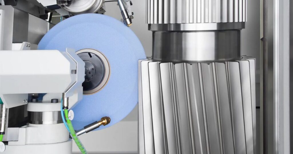
Gear profile grinding — also called form grinding — cuts each tooth gap individually using a grinding wheel whose cross-section precisely matches the designed tooth space geometry. The wheel is dressed to the required profile, then fed axially through each gap in sequence until the full gear is finished.
This is a non-generative process: the wheel does not roll in mesh with the workpiece. That distinction matters, because it means the wheel geometry can be any shape the dresser can produce — standard involutes, asymmetric profiles, crowned flanks, or entirely custom forms.
Profile grinding is the process of choice for:
- Hardened workpiece materials — carburized and hardened steel (58–62 HRC), superalloys, and high-hardness metal alloys where pre-grinding soft-machining distorts under heat treatment
- Non-standard tooth geometries — asymmetric profiles, herringbone gears, hypoid gears, and other forms that exceed generating grinding’s geometric reach
- Small-to-medium batch production — where changeover speed (a wheel swap or program call) outweighs the cycle-time advantage of generating methods
- Shoulder-interference gears — 30 mm-diameter wheels can reach tooth gaps that worm wheel grinding cannot access
Profile Grinding vs Generating Grinding
The two dominant precision gear grinding methods each occupy a distinct niche. Understanding the difference is essential when specifying equipment.
| Factor | Profile (Form) Grinding | Generating Grinding |
|---|---|---|
| Wheel shape | Dressed to tooth space geometry | Worm-shaped grinding wheel |
| Motion principle | Gap-by-gap sequential | Rolls in mesh with workpiece |
| Geometry freedom | Virtually unlimited — any dresser-producible shape | Standard involutes; limited on non-involute forms |
| Changeover speed | Fast — program call + wheel redress | Slower; requires setup change for new profile family |
| Access-restricted gears | ✓ 30 mm wheels reach tight gaps | ✗ Worm wheel requires radial clearance |
| Achievable DIN grade | 2–4 | 3–5 (standard configurations) |
| Best fit | High-mix / low-volume, prototypes, non-standard profiles | Dedicated high-volume lines, standard spur/helical gears |
For high-mix, low-volume production, prototype runs, or any gear geometry outside the standard involute envelope, a gear profile grinding machine offers a decisive advantage. For dedicated high-volume lines producing one or two standard gear families, generating grinding may deliver better throughput per machine-hour.
Industry Applications
Automotive Gear Grinding
Automotive transmission and driveline gears — case-hardened to 58–62 HRC — must meet DIN grade 3–4 tolerances across millions of production cycles. An automotive gear grinding machine running in profile mode handles both spur and helical geometries with the repeatability that OEM supply chains demand. Profile grinding also accommodates the crowned and modified flank geometries used to reduce NVH in modern automatic and dual-clutch transmissions.
Aerospace and Defense
Aerospace gearboxes operate under continuous high-load and high-temperature conditions where a few microns of profile error translate directly into efficiency loss, vibration, and reduced service life. Superalloy and titanium alloy workpieces — common in turbine accessory drives and helicopter transmissions — require the controlled grinding forces and precise wheel dressing that a rigid, high-specification gear profile grinding machine provides. DIN grade 2–3 is the standard target.
Rail Transit
Traction gearboxes in locomotives and EMUs run under sustained load cycles that make gear accuracy a service-life multiplier. Profile grinding ensures the tooth lead and involute form accuracy required for quiet, reliable operation over decades of in-service loading.
Mold Manufacturing and Precision Instruments
Custom gear profiles in mold actuation mechanisms and instrument drives often deviate from standard module series. Profile grinding replicates any designed tooth geometry with micron-level fidelity, making it the only viable finishing process for these applications.
Application Spotlight: Automotive Dual-Clutch Transmission Gear
A driveline component supplier needed to finish-grind helical gears for a 7-speed dual-clutch transmission. Workpiece specification: 20MnCr5 carburized and hardened to 60 HRC, module 2.0, 42-tooth helical gear with crowned flank modification. Accuracy target: DIN 3962 grade 3 (fα ≤ 4 μm, fβ ≤ 5 μm).
Generating grinding was evaluated first but could not consistently hold the crowned flank geometry on a mixed-model line running four gear families at 60–120 parts each. Switching to profile grinding reduced per-family setup time from 45 minutes to under 12 minutes, enabled by the wheel profile library and HSK quick-change interface. CMM inspection confirmed DIN grade 3 on all geometric parameters across a 200-part pilot run, with process capability Cpk > 1.33 on fα.
Key takeaway: on short-to-medium runs with crowned or modified flank geometries, profile grinding’s changeover advantage more than offsets its longer cycle time per piece.
Gear Types a Profile Grinding Machine Processes
A modern gear profile grinding machine handles the full range of cylindrical and non-cylindrical geometries from a single setup platform:
- Spur gears — any module, high accuracy, high throughput
- Helical gears — coordinated rotary and linear axis interpolation controls lead angle
- Splines — internal and external, including crowned and modified splines
- Worm gears and screws — tight lead and profile tolerances achieved with automatic dressing
- Herringbone gears — double-helical forms requiring precise wheel head positioning
- Hypoid gears — complex 3D profiles ground via multi-axis interpolation
- Asymmetric tooth profiles — independent drive-side and coast-side pressure angles
This breadth lets a single CNC gear grinding machine replace multiple dedicated grinding cells in job shop or contract manufacturing environments.
Machine Features That Determine Output Quality
Selecting a CNC gear grinding machine means evaluating the subsystems that directly control accuracy, flexibility, and running cost.
Spindle System
A stepless variable-speed spindle — operating up to 15,000 RPM, switchable between constant-torque and constant-power modes — maintains optimal wheel surface speed across the full diameter range as wheels wear down. HSK taper shank tooling enables sub-minute wheel changes without touching the spindle, which is the critical enabler for high-mix operation: swap the shank, call the program, and grind.
Workpiece Axis
A torque-motor direct-drive workpiece axis in full closed-loop eliminates the backlash and compliance that mechanical transmission introduces into the rotary drive chain. This is the single most important structural factor in tooth-to-tooth pitch accuracy. A 6-axis closed-loop architecture extends that same rigidity across every controlled motion in the machine.
Intelligent Wheel Dressing System
Entering module, pressure angle, and modification parameters generates the required wheel cross-section automatically. The system then dresses, forms, and re-dresses without operator intervention. A wheel library stores finished profiles so repeat jobs skip re-dressing entirely — protecting both cycle time and abrasive wheel cost.
Online Measurement
An integrated measurement system inspects tooth geometry between grinding passes and feeds correction data directly back to the CNC. The loop closes in-process rather than waiting for post-process CMM results, which means fewer rework cycles and faster first-article approval.
Control System
A high-end CNC platform with fast servo response and active interference rejection holds axis positions under the variable grinding forces that material hardness variation and wheel loading generate. Without this stability, maintaining DIN grade output across a production run is unreliable.
Precision Grinding Performance
A correctly configured gear profile grinding machine routinely achieves DIN 3962/3963 grade 2–4 for tooth profile form error (fα), lead error (fβ), and pitch error (fp). Achievable grade depends on:
- Dresser geometry accuracy and diamond tool condition
- Workpiece clamping rigidity and arbor runout
- Machine thermal stability and compensation strategy
- Coolant flow volume, temperature control, and chip evacuation efficiency
For grade 2 output, temperature-controlled environments and vibration-isolated foundations supplement the machine-level controls.
What to Evaluate When Selecting a Gear Grinding Machine Manufacturer
When procurement and engineering teams assess gear grinding machine manufacturers, the following checklist aligns technical capability with production requirements:
- Axis count and closed-loop architecture — minimum 5 axes; 6-axis full closed-loop preferred for production use
- Spindle speed range and interface standard — HSK taper with ≥12,000 RPM for broad wheel-diameter flexibility
- Wheel dressing automation — does the system generate profiles from parameters, or does the operator dress manually?
- In-process measurement integration — on-machine probing with real-time CNC feedback, not offline only
- CNC platform and support footprint — open platform or proprietary; local spare part availability and service response time
- Application engineering support — can the manufacturer provide grinding parameter guidance for your specific gear geometry, module, and material?
Gear profile grinding machine price is not a list-price comparison. Axis count, maximum workpiece envelope, spindle power class, and automation interface level drive significant cost differences. Specification-matched quotations, not catalog prices, are the valid basis for budget planning.
Frequently Asked Questions
What is the difference between profile grinding and generating grinding?
Profile grinding dresses the wheel to the exact tooth space geometry and grinds each gap sequentially. It handles any tooth form — including non-involute and modified profiles — but is slower per piece than generating grinding. Generating grinding uses a worm-shaped wheel rolling in mesh with the workpiece to generate the involute; it is faster for high-volume standard gears but cannot handle non-standard profiles. See the comparison table above for a full side-by-side breakdown.
What DIN accuracy grades can a gear profile grinding machine achieve?
A correctly configured machine routinely achieves DIN 3962/3963 grade 2–4. Grade 2 output requires temperature-controlled environments and vibration-isolated foundations in addition to machine-level controls. Grades 3–4 are achievable under standard production conditions with proper clamping, dresser maintenance, and coolant management.
Which gear types can a profile grinding machine process?
Modern profile grinding machines process spur gears, helical gears, internal and external splines, worm gears and screws, herringbone gears, hypoid gears, and asymmetric tooth profiles — all from a single setup platform. This breadth makes one machine capable of replacing multiple dedicated grinding cells in job shop environments.
How do I choose between profile grinding and generating grinding for my application?
Choose profile grinding when your production mix includes non-standard profiles, crowned or modified flanks, access-restricted geometries, or frequently changing gear families. Choose generating grinding for dedicated high-volume lines producing standard involute spur or helical gears where cycle time per piece dominates total cost. For mixed production environments, profile grinding typically offers better ROI due to changeover flexibility.
What drives gear profile grinding machine price differences?
Gear profile grinding machine price is primarily driven by axis count, maximum workpiece envelope, spindle power class, level of dressing automation, and in-process measurement integration. A 6-axis production center with automatic dressing and on-machine probing is priced substantially above an entry-level 5-axis machine. Request specification-matched quotations — not catalog list prices — as the valid basis for budget planning.
Summary
A gear profile grinding machine is purpose-built for manufacturers who require DIN grade 2–4 accuracy on hardened, complex, or non-standard gear geometries that hobbing and generating grinding cannot reliably produce. From helical gear grinding for automotive transmissions to worm gear and spline production for aerospace and rail applications, the machine configuration — spindle, workpiece axis, dressing system, and control architecture — determines part quality, throughput, and cost per piece.
U·Bright Solutions supplies gear profile grinding machines with full application engineering support for customers in automotive, aerospace, rail transit, and precision manufacturing. Contact us at info@ubrightsolutions.com or contact our team to discuss gear geometry, material, and tolerance requirements.
Verification List
- Deutsches Institut für Normung (DIN). DIN 3962: Tolerances for Cylindrical Gear Teeth — Tolerances for Deviations of Individual Parameters. Beuth Verlag, 1978.
- Deutsches Institut für Normung (DIN). DIN 3963: Tolerances for Cylindrical Gear Teeth — Tolerances for Working Deviations. Beuth Verlag, 1978.
- International Organization for Standardization. ISO 1328-1: Cylindrical Gears — ISO System of Flank Tolerance Classification — Part 1: Definitions and Allowable Values of Deviations Relevant to Flanks of Gear Teeth. ISO, 2013.
- Klocke, Fritz, and Christian Brecher. Gear and Transmission Technology: Fundamentals, Calculation, Materials, and Construction. Springer Vieweg, 2016.
- Rowe, W. Brian. Principles of Modern Grinding Technology. 2nd ed. William Andrew / Elsevier, 2014.
- Brinksmeier, E., J. C. Aurich, E. Govekar, C. Heinzel, H.-W. Hoffmeister, F. Klocke, J. Peters, R. Rentsch, D. J. Stephenson, E. Uhlmann, K. Weinert, and M. Wittmann. “Advances in Modeling and Simulation of Grinding Processes.” CIRP Annals — Manufacturing Technology, vol. 55, no. 2, 2006, pp. 667–696. https://doi.org/10.1016/j.cirp.2006.10.003