
A gear deburring process is not simply a final brushing or grinding pass. It is a controlled sequence that identifies where burrs form, presents each tooth consistently to the tool, removes material without overgrinding the tooth surface, and verifies the result. For gears produced by hobbing, shaping, or grinding, the process has to account for tooth position, edge geometry, contact force, tool path, and inspection feedback together.
Why gear burr removal is a gear-process problem
Burrs can form at the tooth tip, tooth root, and tooth flank when cutting forces change abruptly, the tool wears, or material plastically flows at an exit edge. Their size and shape depend on the cutting direction, tooth geometry, material behavior, and the condition of the preceding operation. Treating every burr as the same defect leads to an unstable process: a tool may remove a visible edge on one tooth while leaving a folded burr at another.
The useful question is therefore not “which deburring tool is strongest?” It is “what contact and verification logic makes removal repeatable across the complete gear?”
Key takeaways
- A gear deburring process must address burr location, tooth access, contact consistency, removal path, and verification as one loop.
- Flexible compliance helps absorb small assembly and workholding deviations, but it does not replace correct locating or path planning.
- Force feedback limits overgrinding risk by controlling contact behavior; visual inspection confirms whether the intended edge condition was reached.
- A reported result from one source test should remain tied to its sample, tooling, and test method. It is not a universal performance guarantee.
Table of Contents
- Why gear burr removal is a gear-process problem
- Where gear burrs form and why location matters
- How a flexible deburring head maintains contact
- Locating and synchronizing the gear
- Force control and visual feedback in the loop
- A practical gear deburring process sequence
- Gear surface finishing and final verification
- How to verify the finished tooth edges
- Process limits and common failure modes
- Planning a gear deburring machine cell
- Frequently asked questions
- What evidence should be retained for a process release?
- Conclusion
- References
Where gear burrs form and why location matters
The same gear can present different deburring conditions around its circumference. Burrs at a tooth tip may be exposed to a tool from several approach directions, while a tooth-root burr is constrained by the root fillet and the neighboring flanks. A tooth-side burr may be continuous, intermittent, folded, or attached only at the cutting exit. The process needs a path and tool attitude that match the actual defect rather than a nominal tooth outline.
The preceding operation also matters. Hobbing, shaping, and grinding produce different edge conditions because their cutting directions, tool engagement, and exit behavior differ. Tool wear can change the burr distribution before the operator notices a change in the finished gear. A stable cell therefore links the deburring recipe to the upstream operation and keeps the inspection result traceable to the part and process state.
For process planning, divide the problem into four observations:
- Burr location: tooth tip, root, flank edge, bore edge, or another transition.
- Burr attachment: loose, continuous, folded, smeared, or locally raised material.
- Access geometry: the clearance available to the tool, holder, and workholding.
- Acceptance condition: the edge state that is acceptable without damaging the involute, root fillet, or functional datum.
This map prevents a common mistake: increasing tool pressure to compensate for an incorrect path. More pressure can remove a stubborn burr, but it can also round a functional edge or alter the tooth surface.
How a flexible deburring head maintains contact
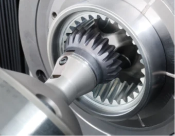
A rigid tool follows the programmed path even when the gear, fixture, or tool assembly contains small deviations. On a complex tooth surface, that can produce two opposite defects: insufficient contact that leaves burr material behind, or excessive contact that removes sound tooth material. A flexible deburring head introduces compliance so the tool can accommodate limited variation while maintaining a more consistent engagement condition.
Compliance does not mean uncontrolled motion. The head still needs a defined nominal path, an allowable deflection range, and a way to detect abnormal loading. Flexible couplings and elastic supports can absorb micro-vibration and small assembly errors, while a constant-force arrangement can regulate the contact force applied to the tooth edge. The mechanical compliance and the control strategy have to be designed together.
The tool form is also part of the process. A brush, abrasive wheel, or other deburring medium reaches a different portion of the tooth edge and creates a different surface interaction. The selection should follow the burr type and the acceptance condition, not the name of the machine. A tool that is appropriate for a loose edge burr may be unsuitable for a folded burr close to a functional flank.
Locating and synchronizing the gear
Deburring quality depends on locating the gear before the tool begins. A self-centering fixture can establish a repeatable radial relationship, while an angular encoder or equivalent reference can align the tooth position with the programmed path. The objective is not merely to hold the part; it is to make the relationship between the measured gear and the tool path known.
A locating error can appear as a deburring error. If the part is slightly off-center, the tool may touch one tooth more heavily than another. If the angular reference is wrong, a path intended for a tooth tip may approach a flank transition. These errors are especially difficult to diagnose when the cell has no record of the locating state.
A robust sequence is to locate, confirm, and then synchronize:
- Locate the gear against defined radial and axial references.
- Confirm presence, seating, and orientation before motion.
- Establish the angular relationship between the gear and the programmed tooth path.
- Keep the tool approach and retract path clear of the fixture and adjacent features.
- Record the part identity and process state with the inspection result.
This is why automation is more than adding a robot to a manual deburring operation. Automatic loading, locating, motion, inspection, and data recording have to share a coordinate and decision model.
Force control and visual feedback in the loop
A gear deburring process becomes more reliable when force and vision answer different questions. Force feedback describes the interaction between tool and workpiece: whether contact is present, whether loading is stable, and whether an unexpected obstruction or excessive engagement has occurred. Vision describes the resulting edge condition: where burr material remains and whether the finished surface matches the acceptance rule.
A closed-loop strategy can use the force signal to adjust pressure or feed behavior while the tool is engaged. A visual system can then inspect the tooth surface, enhance relevant edges, segment the burr region, and classify the result against a defined threshold. The controller can continue, alter the path, request a second pass, or stop for an operator decision.
The important boundary is that a sensor does not create a valid process by itself. A force signal needs a calibrated interpretation, and a vision result needs controlled lighting, a stable viewpoint, and an acceptance rule that distinguishes a burr from normal tooth geometry. The process should document the signal used, the decision made, and the condition that triggered it. During a development run, compare at least the pre-pass and post-pass edge state for the same tooth locations, tool condition, and inspection viewpoint; this establishes a traceable baseline without pretending that one sample proves production capability.
A layered control architecture is often useful:
| Layer | Responsibility | Typical evidence |
|---|---|---|
| Motion and safety | Executes the approved path and protects the machine and part | Position, interlock, and alarm state |
| Contact control | Maintains the intended tool-work interaction | Force, motor current, or displacement trend |
| Inspection | Determines whether the edge condition meets the rule | Image, measured feature, and pass/fail result |
| Production record | Makes the outcome traceable | Part identity, recipe revision, and inspection record |
A practical gear deburring process sequence
A process can be organized into the following steps, with the exact recipe established on the actual gear and tool combination:
- Characterize the burr. Identify the operation that created it, its location, its attachment, and the edge condition that must remain intact.
- Define the workholding reference. Establish how the gear is centered, seated, and indexed, and how the datum is checked.
- Select the contact method. Match the tool medium, contact orientation, and compliance to the burr and tooth geometry.
- Plan the approach and retract. Simulate the tool, holder, fixture, and neighboring features through the complete motion.
- Set the nominal engagement. Define the path, feed behavior, and allowable contact response from a controlled trial, not from a generic machine label.
- Run the controlled pass. Use force or equivalent feedback to detect abnormal contact and protect the tooth surface.
- Inspect the result. Check the targeted edge and any surfaces at risk of overgrinding.
- Decide the disposition. Release, repeat a bounded corrective pass, or stop for investigation according to the documented rule.
- Record the evidence. Store the recipe revision, inspection result, and any exception against the part or batch.
This sequence separates process development from production repetition. During development, the team may change the tool path and contact strategy. During production, those decisions should be controlled revisions with clear limits.
Gear surface finishing and final verification
Gear surface finishing is the final control layer after burr removal. It should confirm that the tooth edge is clean without turning a deburring pass into an uncontrolled stock-removal operation. Check the functional tooth surfaces, root transition, edge condition, and any specified visual or dimensional limits with a method suited to the part.
The inspection result should identify the gear family, recipe revision, tool condition, and disposition. This record helps distinguish a surface-finishing problem from a locating problem or an upstream burr-generation change.
How to verify the finished tooth edges
Inspection should be designed around the defect and the function of the gear. A visual check can locate residual burrs and obvious edge damage, but it may not be sufficient for a high-precision application. Magnified inspection, dimensional measurement, surface assessment, or a functional check may be required depending on the acceptance specification.
Use a verification plan that answers three questions:
- What feature is measured? For example, residual burr presence, edge break, tooth profile condition, or surface damage.
- Where is it measured? Sampling must cover the tooth locations and areas most likely to vary.
- What decision follows? The threshold must distinguish release, rework, and escalation.
The source material for this article reports a controlled comparison using a specific gear sample and a specific test setup. Those reported values are useful as an example of how a study can be structured, but they should not be carried into a production claim without the sample count, initial burr distribution, tool details, force setting, measurement uncertainty, and statistical method. Record those details for the actual part before using a result as a release decision.
Gear burr removal acceptance checks
The acceptance check for gear burr removal should cover residual material and damage to functional surfaces.
Separating gear burr removal from surface finishing
Gear burr removal targets unwanted attached material at an edge. Gear surface finishing is broader: it may include the final condition of the tooth flanks, root transition, and edge break after removal. Keeping those decisions separate makes the process easier to validate and prevents a finishing step from quietly changing the functional geometry.
Process limits and common failure modes
The main limits are usually geometric and evidentiary rather than a single universal machine rating. A tool may not clear an adjacent shoulder or fixture feature. A root fillet may be too constrained for the selected medium. A flexible head may have insufficient travel or may deflect beyond its controlled range. A vision system may not distinguish burr material from a normal edge under changing light or surface condition.
Common failure modes include:
- Residual burrs: the path misses the defect, contact is too light, or the burr morphology changed upstream.
- Overgrinding: contact pressure, deflection, or dwell is too high for the functional tooth edge.
- Uneven removal: locating or angular synchronization varies around the gear.
- False inspection decisions: lighting, focus, reflections, or an incomplete acceptance rule distort the image result.
- Untraceable rework: a second pass is made without recording the reason or recipe revision.
Each failure mode points to a different corrective action. More abrasive force is not a general solution. The investigation should first determine whether the cause is burr generation, location, contact, motion, sensing, or decision logic.
Planning a gear deburring machine cell
Before specifying a cell, review the complete production context. The gear family, upstream process, material, tooth geometry, production mix, workholding references, inspection requirement, and data system all affect the process design. A cell that works for one gear should not be described as universal until the relevant family boundaries have been demonstrated.
When comparing a gear deburring machine, compare the complete control loop rather than a model label. Check tool access, locating, compliance range, force or displacement feedback, visual inspection, recipe control, and traceability together. A machine with a faster motion profile is not necessarily the better choice if it cannot prove the finished edge condition.
Document at least these items:
- Gear deburring machine selection: compare access, locating, compliance, feedback, inspection, and traceability requirements rather than choosing by a model label.
- Gear geometry and the burr locations that need treatment.
- Upstream operation and the expected variation in burr morphology.
- Fixture datum, centering method, indexing reference, part-presence checks, and the controlled operating window for the approved recipe.
- Tool medium, compliance range, approach path, and retract clearance.
- Force or displacement feedback and the abnormal-contact response.
- Vision conditions, inspection features, acceptance thresholds, and sampling plan.
- Recipe revision, traceability fields, rework logic, and operator escalation.
This documentation makes it possible to compare a new gear family against a proven process without hiding the assumptions that control quality. It also gives maintenance and quality teams a shared language for diagnosing drift.
Frequently asked questions
What is a gear deburring process?
A gear deburring process is a controlled sequence for locating burrs on a gear, presenting the tooth edges to a suitable tool, regulating contact, inspecting the result, and recording the disposition. Its purpose is to remove unwanted material while preserving the tooth profile, root geometry, and other functional surfaces.
Why is force control useful in gear deburring?
Force control helps manage how firmly the deburring tool contacts the gear. It can reduce sensitivity to small fixture or assembly deviations and identify abnormal loading. It does not replace correct locating, tool selection, path planning, or inspection, and its limits must be established on the actual part and tooling.
Can vision inspection replace a deburring trial?
No. Vision can detect residual burrs or edge conditions after a pass, but it cannot by itself establish a safe tool path or prove that the process will not overgrind the tooth surface. A controlled trial is still needed to connect tool motion, contact behavior, and inspection results.
Should one deburring recipe be used for every gear?
Only when the relevant gear family and process boundaries have been demonstrated. Tooth geometry, material, upstream burr formation, workholding, tool access, and acceptance criteria can change the required path and contact condition. A recipe should be validated for the parts it is intended to cover.
What evidence should be retained for a process release?
Retain the part identity, upstream operation, burr map, fixture datum, recipe revision, tool condition, contact signal, inspection images or measurements, and any rework disposition. Together, these records show whether a later variation began in burr generation, workholding, contact control, inspection, or the release decision.
Conclusion
A dependable gear deburring process links burr characterization, repeatable locating, flexible tool contact, force feedback, visual inspection, and traceable disposition. The central engineering task is to control the relationship between the tooth edge and the tool throughout the pass, then verify that the resulting edge condition meets a defined requirement. Source-reported results can illustrate a test method, but they must remain bounded by the sample and setup that produced them.
For help reviewing a gear deburring cell around a specific part family, workholding reference, inspection requirement, and production workflow, contact UBright Solutions.
References
- The Formation and Properties of Machining Burrs — background on burr-formation mechanisms and the relationship between machining conditions and burr properties; not a gear-specific production prescription.
- Deburring, Defined — a gear-industry discussion of tool media, floating-head contact, and automation options; not a universal process result.
- The Electrochemical Process for Gear Deburring — an example of a gear-specific deburring route with stated applicability limits; not a claim that the method suits every gear.