
Axle shaft flange forging turns the plain end of a bar into the wheel-end flange of a drive axle, and how that flange is formed decides how the metal fibres run through the finished part. Two routes dominate: axial upsetting, which compresses the whole cross-section at once, and orbital forging, in which a tilted die rocks around the face and works a small area at a time. Same shape, different flow geometry. This guide is for forging engineers, axle plant process owners and drivetrain buyers who have to justify one route over the other on mechanical grounds rather than on catalogue claims.
Direct answer. The flange is formed either by compressing the whole bar end at once, which is upset forging, or by rocking a tilted die around the face, which is orbital forging. The first lays grain flow down as a continuous radial fan more or less by geometry. The second reaches the same outline with far lower press force, but works the same metal repeatedly from changing directions. Flange geometry and the axle’s loading case decide which of those is acceptable.
What this article does not cover: press tonnage selection, equipment models and supplier comparison. Those depend on a specific part drawing and belong in a quotation, not in an explainer.
Last reviewed: August 2026.
Table of Contents
- Axle shaft flange forging in one answer
- Why the flange, not the shaft, sets the process
- Grain flow: what the term means on a flanged part
- Radial grain flow in discs and flanges
- The three rules that bound a single upsetting stroke
- Upset forging: axial compression, one continuous fan
- Orbital forging: a tilted die and a travelling contact
- Reading the two flow patterns at the fillet
- Three flange geometries that change the answer
- Where flow-related defects actually appear
- A specification checklist for axle shaft flange forging
- Frequently asked questions
- Where this fits in a full axle shaft line
- How this comparison was assembled
- Talk to UBright about your flange forging process
Axle shaft flange forging in one answer
Short version: the process succeeds or fails on how the metal is gathered and on how the resulting fibre pattern crosses the flange-to-shaft fillet. Upsetting fans the fibres outward in one continuous pass and wraps the fillet without interruption. Orbital forging reaches the same outline at far lower force, but builds a helical path instead of a radial one. Neither is automatically wrong; part duty and flange geometry decide.
Why the flange, not the shaft, sets the process
A drive axle shaft is mostly a slender bar, and turning, splining and heat treating that bar is well-trodden ground. The flange is where the process choice lives, because it demands that a large volume of metal end up at one end of a comparatively thin bar.
That volume is gathered by upsetting a heated length of bar so the diameter grows and the length shrinks. WeForging states the mechanism plainly: the billet is compressed between dies so the metal expands to the required shape, increasing cross-sectional diameter while reducing length. Nothing in the final die can compensate for metal that was never gathered.
So the difficult engineering sits upstream of the shape you actually want. A shallow flange on a fat bar needs almost no gathering; a broad flange on a slim bar needs several steps before any cavity closes, and each one must leave a preform the next step can accept without folding.
The three rules that bound a single upsetting stroke
Upsetting is not open-ended, and the limits are numeric. The Open University’s OpenLearn manufacturing reference states three of them:
- The length of unsupported metal that can be upset in one stroke without serious buckling must not exceed three times the bar diameter (3d).
- The maximum increase in cross-section obtainable at a single stroke is 1.5 times the bar diameter.
- Upsets longer than 3d can be formed, but they require a recess in the heading tool.
Those limits are the arithmetic behind the word “gathering”. A flange that must grow well beyond 1.5d cannot be reached in one stroke, so the volume is accumulated across several stations — and the number of stations, not the final cavity, sets the cycle.
This is also why the two competing routes are not simply “one press versus another press”. They gather differently, they hold heat differently, and they impose different limits on what the flange outline can be.
The load duty behind the geometry
The flange is not decorative. It carries the wheel-end connection, so the loading case on the shaft is the reason the flange exists at all — and the two common axle architectures load it very differently.
In a semi-floating axle the shaft itself carries the vehicle weight; DieselHub’s axle explainer is direct about the consequence, stating that the weight of the vehicle and any cargo must be carried by the axle shaft itself, which subjects it to bending moment, shear force and torsional force. In a full-floating axle the weight of the vehicle and its cargo is transferred to the axle tube rather than the axle shaft itself, so the shaft is not subjected to the bending moment or shear force.
That matters because bending and torsion load the flange-to-shaft transition in different directions. A shaft that only twists asks the fillet to resist torsional shear; a shaft that also bends asks the same fillet to survive a reversing bending stress on every wheel revolution. Fibre orientation across that fillet is the direct answer to the loading case, not a cosmetic metallurgical point.
Grain flow: what the term means on a flanged part
Grain flow is the directional structure left behind when metal is deformed hot. The forging literature uses grain flow for the phenomenon and fibre for the individual lines, and this article follows that convention. All Metals & Forge Group describes it as grains elongating and realigning to follow the geometry of the part, produced deliberately through controlled compressive forces and multiple forging steps rather than as a by-product.
The reason the industry cares is fatigue. Aligned grain flow improves resistance to cyclic loading and fatigue failure, and the effect is strongest in rotating components such as shafts and gear blanks. The mechanism is not exotic: an elongated fibre structure is anisotropic, and a crack has a harder time propagating across fibres than along them. Orienting the fibres along the primary stress path is how a forging outperforms a part cut from bar or plate of the same grade.
That is where the argument for forging a flange at all comes from. Manufyn’s forging design guide cautions against heavy machining that removes forged skin with aligned grain or cuts through load-bearing grain paths. A flange machined out of oversized bar has fibres running straight through it and terminating at every machined face; a forged flange has fibres that turn with the part.
Radial grain flow in discs and flanges
Disc-shaped and flange-shaped features get their own flow category. Radial grain flow occurs when material flows outward from a central point, so the grain lines radiate outward — a pattern that improves performance in components subjected to rotational or radial loading.
An axle flange is exactly that case: a disc on the end of a shaft that rotates under load and transmits torque through its bolt circle. A radiating fibre pattern puts fibre length in the direction the torque is carried and keeps fibres continuous where the disc meets the shaft.
Two criteria follow, and they are the ones worth arguing about in a process review:
– Continuity across the fillet. Fibres pass from shaft into flange without being cut or folded at the transition. – Orientation matching the duty. Fibres radiate in the plane that carries torque, rather than wandering in directions no load follows.
Upset forging: axial compression, one continuous fan
Upset forging works the whole cross-section at once. The heated end of the bar is compressed along its own axis between dies, the material expands outward, and the head or flange forms. Because the compression is axial and the die face is flat, every element of the bar section moves outward together.
The lineage explains the machines. Thomas Oliver built the first machine for forging bolts in England, a treadle-operated hammer known as the Oliver hammer, and bolt production using it began in Darlaston, Staffordshire in 1838. OpenLearn records that the technique was originally developed for heading bolt heads and has since been widened to produce components such as flanged shafts and preforms for finish forging, which is exactly the axle case.
Geometrically, that produces the fan pattern in the left half of the figure above. Material near the bar axis stays near the flange centre. Material near the bar surface travels furthest and ends up near the flange outside diameter. Between those extremes the fibres spread smoothly, and because nothing reverses direction, the lines stay continuous from the shaft, around the fillet, and out to the rim.
WeForging’s process note makes the same point about the result rather than the mechanism, noting that the process maintains continuous grain flow and that this improves fatigue resistance and impact strength, with fibre alignment following the direction of deformation.
The engineering cost of that clean pattern is force. Compressing the full section at once means the press has to supply load proportional to the whole contact area. That is the trade the alternative route exists to avoid.
Two secondary effects follow. One short stroke means little contact time with cold tooling, so temperature loss during forming is small. And because the cavity is closed by a die rather than swept by a moving tool, the flange outline is whatever the cavity is — including outlines that are not circular.
Orbital forging: a tilted die and a travelling contact
Orbital forging — also called rotary or rocking-die forging — replaces the flat die with one that is tilted and moving. Total Materia describes the upper die travelling in an orbital path with its axis tilted at specific angles, typically 1–2 degrees, while performing rotary motion, so the upper tool revolves on an inclined axis and applies force to a small portion of the work at any given time.
The consequence is a much smaller instantaneous contact patch. The same reference notes that greater tilt angles give smaller contact surfaces and correspondingly lower forming loads, so the design needs considerably smaller presses than classical forging. Jin, Gu and Hua, writing in Advances in Mechanical Engineering, report the same relationship: the forces used in cold orbital forging are much smaller than in traditional upsetting. That is a real advantage — a smaller press is cheaper to buy, to foundation and to run.
The geometric price is visible in the right half of that figure. Because the contact patch travels around the face instead of pressing everything at once, a given element of metal is deformed many times, each time in a different local direction, so the fibre path is helical rather than radial. Near the outside diameter this matters little; the metal is pushed outward regardless. Near the centre, where the travelling contact passes closest to the axis on every orbit, the same material sees repeated reversals.
What the public record does and does not support
This is where equipment marketing tends to overstate on both sides, so it is worth being precise.
Supported: orbital forging needs less force, uses smaller presses, and is well established for disc- and flange-shaped parts. Total Materia also credits hot forging generally with sealing internal cracks, eliminating voids, and breaking up and redistributing inclusions.
Not supported: a blanket claim that orbital forging ruins grain flow. The published work on cold orbital forging of flange gears is preform-design work — the effort goes into shaping the preform so the material arrives correctly, which says flow control is demanding, not impossible.
The honest formulation is a process window, not a verdict. Upsetting produces the radial pattern more or less by geometry. Orbital forging produces an acceptable pattern when preform, tilt angle, feed rate and total stroke are matched to the part, and a disturbed core when they are not.
Reading the two flow patterns at the fillet
The flange-to-shaft fillet is where the two patterns can be compared meaningfully, because that is where the section changes fastest and where the service stress concentrates.
| Aspect | Axial upsetting | Orbital forging |
|---|---|---|
| Contact during forming | Full face, single stroke | Local patch, travelling around the face |
| Forming load | Proportional to full section | Substantially lower for the same part |
| Fibre path in the flange | Radial fan, outward from the axis | Helical, built up over many orbits |
| Fibre path across the fillet | Continuous, wraps the radius | Continuous, but with repeated direction changes |
| Flange centre | Worked once, in one direction | Worked repeatedly, in changing directions |
| Sensitivity to preform accuracy | Moderate | High — preform design is the published research topic |
| Non-circular outlines | Set by the die cavity | Constrained by the rotational motion |
Read that as where risk sits, not as a scoreboard. For a plain disc on a heavy shaft carrying pure torque, either route can be specified with confidence and the smaller press is a real saving. For a thin flange, or one on a shaft that also carries bending, the centre-of-flange behaviour stops being academic.
Three flange geometries that change the answer
Process arguments collapse once the part drawing is on the table, because flange geometry decides how much gathering is needed and whether rotational forming applies at all.
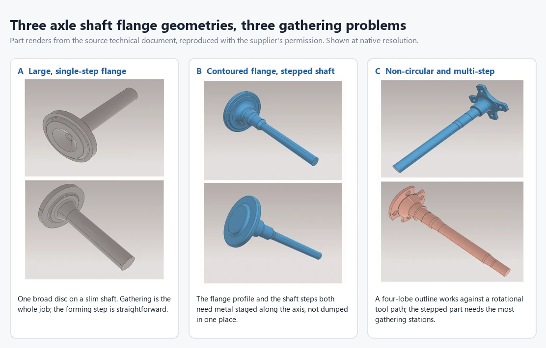
A. Large, single-step flange. One broad disc on a slim shaft. Almost all the difficulty is gathering, since the volume must be accumulated from a much smaller bar diameter before any cavity closes. Once the metal is there, forming is straightforward and both routes are candidates.
B. Multi-step, stepped flange. Several diameters stacked along the axis, so the gathered volume must be staged rather than dumped in one place. The number of gathering operations rises, and each one is another chance for the preform to arrive slightly wrong.
C. Non-circular or thin flange. A forming process built on rotational motion loses its fit when the outline is not a circle. Thin sections compound it: they chill fastest and have the least thermal margin for a slow, multi-orbit cycle. Here the choice is usually made for you.
One constraint cuts across all three. Raised face features such as moulded lettering are formed by a cavity, so if the die never presents a full-face cavity, they have to be produced some other way.
Where flow-related defects actually appear
Defects are the observable end of everything above. HDC Manufacturing puts it bluntly: forging defects usually mean the metal did not flow the way the die designer expected.
Laps and folds. Metal folds onto itself instead of flowing smoothly, or two metal fronts meet without fusing. Documented causes include improper die design, sharp geometric transitions, incorrect billet sizing, inadequate preform design, low forging temperature and lubrication problems. They matter here because these surface seams behave dangerously under cyclic loading — exactly what a wheel-end flange sees.
Underfill. The metal did not fully fill the cavity, leaving missing corners, shallow features or weak edges. Causes include insufficient billet volume, low temperature, inadequate press energy, poor die venting and overly restrictive flow paths. On a stepped flange it usually means the gathering sequence did not stage the volume correctly.
Core disturbance. Specific to the rocking-die route and a process-window issue rather than an inherent flaw: when preform, tilt angle and feed are mismatched, repeated reversals near the flange axis leave the centre worked in inconsistent directions.
Two of the three are preform problems, not forming problems. That is the recurring theme of flange work.
A specification checklist for axle shaft flange forging
Ten questions for specifying a new line or auditing an existing one. Each has a defensible answer, not a preference.
- Axle architecture? Full-floating carries torque only; semi-floating adds bending and shear. This sets the fillet duty.
- Upset ratio? Flange volume against the bar volume it comes from. A large ratio means gathering drives the schedule.
- How many gathering operations? Count them. Each is a re-heat risk and a fold risk.
- Is the outline rotationally symmetric? If not, rotational forming is disadvantaged before anything else is weighed.
- Thinnest flange section? Thin sections lose heat fastest and cap the cycle time.
- Raised face features? Lettering and bosses need a cavity, not a swept tool path.
- Where does the service crack start? If it is the fillet, fibre continuity there belongs on the drawing.
- Machining stock on the flange face? Heavy stock removal erodes the reason for forging the flange at all.
- Is the preform validated or assumed? For the orbital route it is the published research problem — make it a deliverable with acceptance criteria.
- What evidence will you accept? Sectioning and macro-etching a first article shows the real fibre pattern. A quotation shows nothing.
Frequently asked questions
Is upset forging always better than orbital forging for an axle flange?
No. Upsetting produces the radial fibre pattern more directly, but orbital forging reaches the same shape at substantially lower forming loads and is well established for disc and flange parts. The answer depends on flange geometry, section thickness, and whether the shaft carries bending as well as torque.
Can a non-circular flange be orbital forged?
It is the wrong fit. The forming motion is rotational, so a non-circular outline works against the tool path. Forging a round disc and machining the outline afterwards is possible, but it turns forged material into scrap and cuts through the fibre pattern.
Does machining after forging destroy the grain flow benefit?
Partially, and it is a real design consideration. Manufyn’s design guide warns that heavy machining removes forged skin with aligned grain and can cut through load-bearing grain paths, reducing fatigue performance. Near-net flange forming keeps the benefit; generous machining allowance gives it away.
What decides how many gathering steps a flange needs?
The ratio of flange volume to bar volume, and how it must be distributed. Since one stroke cannot increase the cross-section by more than about 1.5d, a large flange needs several stations, and a stepped flange needs more again because the metal must be staged along the axis.
Where this fits in a full axle shaft line
Flange forming sits inside a longer chain, and the neighbouring operations constrain it. Ahead of it the bar is cut and heated, and scale has to be removed between gathering and final forming, because rolled-in scale becomes a surface defect and shortens die life — see our note on the forging descaling machine.
Behind it, everything is machining: the flange face, the bolt circle and the shaft diameters are turned and ground, which is where the machining-allowance question becomes a cost. The same sequencing logic applies to other rotating drivetrain parts — see railway axle machining and the CV joint manufacturing process. A route that arrives near-net reduces the machining that erodes the fibre pattern; one that arrives further from net shape hands the problem downstream.
How this comparison was assembled
Every mechanical claim above traces to a named source in the References section; each page was retrieved and its title checked on 24 August 2026. No equipment-vendor performance figures were used — cycle times, changeover times, staffing counts and maintenance costs quoted by machine builders are commercially motivated, so they were excluded rather than repeated. The two diagrams are parametric drawings of flow geometry: schematics, not metallography, with no measured meaning in the line spacing.
Talk to UBright about your flange forging process
To close the question this article opened with: grain flow decides the route because the flange-to-shaft fillet is where service cracks start, and the two forming methods put fibre across that fillet differently – one by geometry, the other only when the process window is held.
If you are specifying an axle shaft flange forging process — or working out why an existing one folds at the fillet — the useful conversation starts with the part drawing, the axle architecture and the flange volume ratio, not with a machine model.
UBright Solutions builds turnkey manufacturing lines for automotive and drivetrain components, including forging equipment and the machining stations that follow it. Send us the flange geometry and the duty case and we will work through the gathering sequence with you. Contact our engineering team to start that review.
References
- Grain Flow’s Role In The Forging Process — Supports the definition of grain flow as deliberate directional alignment and its effect on fatigue resistance in rotating parts.
- Forging Grain Flow: Strength, Structure & Design Guide — Supports radial grain flow in discs and flanges and the warning that heavy machining cuts through load-bearing grain paths.
- Upset Forging: Process, Applications & Advantages — Supports the description of axial compression increasing diameter while reducing length, and continuous grain flow as the result.
- Orbital Forging: Advanced Manufacturing Process for Superior Metal Components — Supports the 1–2 degree tilted orbiting die, the local contact patch and the resulting lower forming loads.
- Preform designing approach in cold orbital forging of flange gear — Supports that cold orbital forging uses much smaller deformation forces than traditional upsetting, and that preform design is the governing problem.
- Forging Defects: Common Types, Causes, and How to Prevent Them — Supports the described causes of laps, folds and underfill and their link to unexpected metal flow.
- Upset forging — Supports the three single-stroke upsetting limits (3d unsupported length, 1.5d cross-section increase, recess required beyond 3d) and the origin of the process in bolt heading.
- Thomas Oliver (engineer) — Supports the 1838 Darlaston start of machine bolt forging with the Oliver hammer.
- Semi-floating vs Full-floating Axles Explained — Supports which member carries vehicle weight and bending moment in each axle architecture.