
Aluminum machining distortion control is the single biggest obstacle to producing large aerospace structural parts to print. When a monolithic frame is hogged out of a thick pre-stretched plate, material removal can exceed 90%, and the part bends or twists as locked-in stress redistributes. On many programs, first-pass dimensional yield on these parts sits below 80%. This guide explains why aluminum structural parts distort during machining and how a combination of residual stress measurement, FEM cutting simulation, and multi-factor deformation prediction brings that distortion under control.
Table of Contents
- Why aluminum structural parts distort during machining
- Residual stress measurement: the crack compliance method
- FEM cutting simulation for heat–force coupled prediction
- Controlling surface residual stress in high speed milling
- Multi-factor machining distortion prediction
- Business value: lower scrap, higher throughput
- FAQ
- Conclusion
Why aluminum structural parts distort during machining
Machining deformation control starts with understanding the root cause. Distortion in aerospace aluminum alloy machining comes from two stresses acting together: the initial residual stress already locked into the blank, and the new residual stress generated by the cutting process itself.
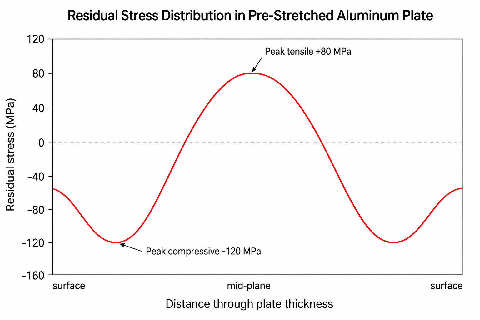
Pre-stretched plate in alloys such as 7050-T7451 and 2024-T3 develops residual stress approaching the yield strength during hot rolling and solution quenching. Pre-stretching relieves most of it, but the plate still holds a characteristic “compressive outside, tensile inside” profile through its thickness. When machining removes material, that equilibrium is broken and the part moves. Add thin walls, low rigidity, and the heat and force of cutting, and you get the bending and twisting that defeats tight tolerances.
Residual stress measurement: the crack compliance method
You cannot control what you cannot measure. The challenge with thick plate is reading stress deep inside the material. Layer-by-layer hole drilling loses accuracy as the hole deepens, and stripped-layer X-ray diffraction is slow and needs heavy correction.
The crack compliance method solves this. A controlled cut is introduced with wire EDM, and the released strain is back-calculated into the full through-thickness stress profile using a 9th-order Legendre polynomial fit. In UBright’s testing this returns a total stress-calculation uncertainty of roughly 2.8 MPa, with the fitted distribution validated against coordinate-measuring-machine data to within about 3%. That accuracy lets you predict distortion risk before a single chip is cut and adjust the machining strategy in advance.
FEM cutting simulation for heat–force coupled prediction
Metal cutting is a strongly coupled heat–force process: uneven cutting force and cutting heat are the direct drivers of in-process deformation. UBright’s FEM cutting simulation, built in Abaqus and Deform-3D, models both 2D orthogonal and 3D oblique cutting and rests on three pillars.
Material, friction, and adaptive-mesh models
The material model uses a Johnson–Cook formulation to capture flow stress at high strain rate (around 10⁵ s⁻¹) and high temperature (up to ~500 °C), calibrated with Hopkinson-bar and orthogonal cutting tests. Chip separation uses a dimensionless Cockcroft–Latham fracture criterion, with the tool–chip interface split into a sticking zone and a sliding (Coulomb friction) zone; the measured friction coefficient runs about 0.31–0.34 across cutting speeds of 600–2000 m/min. Adaptive remeshing keeps the cutting zone accurate, holding simulated cutting force to within roughly 15% of test values.
What the simulation reveals about cutting force and heat
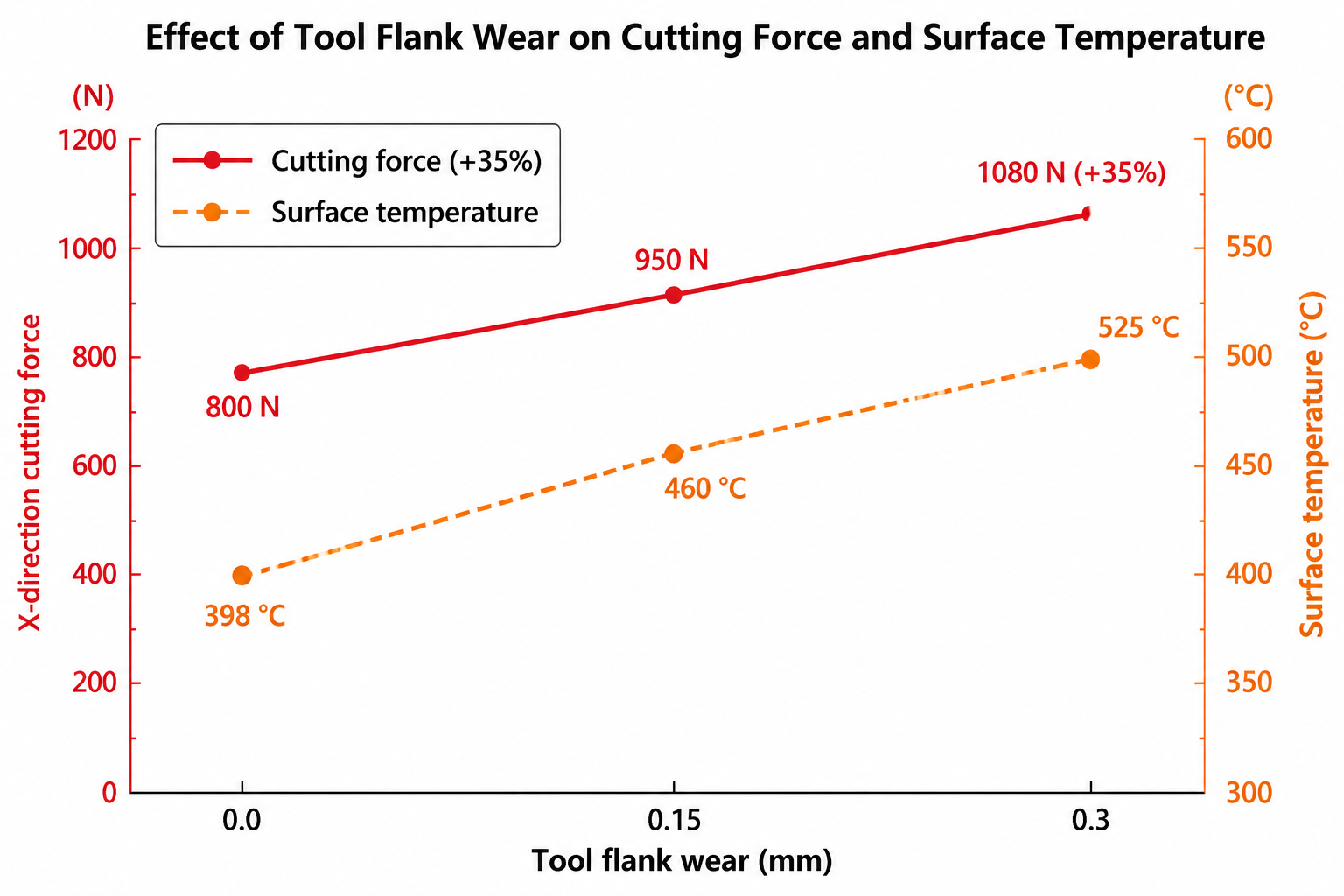
As tool flank wear grows from 0 to 0.3 mm, simulated X-direction cutting force rises about 35% and peak workpiece surface temperature climbs from roughly 398 °C to 525 °C. Increasing the tool inclination angle drives Y-direction force up sharply while Z-direction force stays nearly flat. These quantified relationships let UBright tune cutting parameters to cut peak temperature and hold force fluctuation tight, removing distortion drivers during the process rather than correcting them afterward.
Controlling surface residual stress in high speed milling
High speed milling aluminum alloy leaves a thin residual stress layer, roughly 0.1–0.5 mm deep, that directly affects thin-wall dimensional stability. Studying it with X-ray diffraction (CrKα target) plus electrolytic layer removal reveals clear, usable rules for milling residual stress:
– *Spindle speed. At low speed (around 4000 r/min) the surface holds compressive stress (about -40 to -60 MPa); at high speed (around 16000 r/min) it flips to tensile (about +20 to +40 MPa), and the stressed layer thins from ~0.5 mm to ~0.3 mm. – Tool flank wear. This is the dominant factor. At 0.3 mm wear, surface tensile stress is about 80% higher than with a fresh tool, so wear monitoring and timely tool changes matter. – Tool nose radius.* A small radius (R0.5 mm) introduces tensile stress on the side wall; a large radius (R3 mm) introduces compressive stress.
Mechanically, low-speed cutting is force-dominated and burnishes a compressive layer; high-speed cutting is heat-dominated, and thermal expansion followed by cooling leaves tensile stress. Using a tuned high speed milling parameter set, peak surface compressive stress can be raised by about 25% and part fatigue life extended by roughly 30%.

Multi-factor machining distortion prediction
The final shape error is the coupled result of initial blank stress, cutting force, cutting heat, clamping force, and machining-induced stress. UBright’s machining distortion prediction model accounts for all of these using element birth-and-death to simulate material removal, so you can forecast the deformation trend before cutting.
The model shows that a rectangular plate reaches maximum deflection at about 50% material removal, then deflection reverses as removal continues. Tensile and compressive stress drive bending; shear stress drives twisting, and the twist component is larger than the bend. On process-route choices, an “odd-even diagonal milling” sequence cuts deformation about 40% versus conventional sequential milling, and a double-sided “rough front, flip, rough back, finish back, flip, finish front” route reduces deformation about 35%. Validated against CMM data to within roughly 15%, the model has brought maximum deformation down from about 0.20 mm to 0.08 mm — inside aerospace-grade IT5–IT7 tolerance.
flowchart LR
    A[Measure residual stress<br/>crack compliance method] --> B[FEM heat-force<br/>cutting simulation]
    B --> C[Tune parameters<br/>and process route]
    C --> D[Predict and verify<br/>0.20 to 0.08 mm]
Business value: lower scrap, higher throughput
The point of aluminum machining distortion control is commercial, not just technical. By keeping distortion in check, the straightening step that traditionally touches more than 30% of parts is largely removed. Users report scrap rates falling from around 15% to under 3%, throughput up about 25%, and per-part cycle time shortened roughly 18–25%; some report substantial annual cost savings and strong return on investment after adoption. The approach has been validated with university research partners and proven on real aerospace component lines, and it scales to large monolithic frames and honeycomb structural parts that would otherwise be out of reach.
FAQ
Why does aluminum warp after machining?
Because two stresses combine: residual stress already locked into the pre-stretched blank, plus new stress created by cutting force and heat. Removing material breaks the internal equilibrium, so the remaining part bends or twists toward a new balance.
What is the crack compliance method?
It is a residual-stress measurement technique: a controlled wire-EDM cut releases strain that is back-calculated, via a high-order polynomial fit, into the full through-thickness stress profile of thick plate — more reliably for deep stress than hole drilling or stripped-layer X-ray diffraction.
How does spindle speed affect residual stress?
As a rule of thumb, low spindle speed leaves the surface in compression while high spindle speed flips it into tension and thins the stressed layer. Choose the regime to match part stiffness and fatigue requirements rather than defaulting to the fastest setting.
Can machining distortion be predicted before cutting?
Yes. A multi-factor FEM model combining blank stress, cutting force, heat, clamping, and machining stress can forecast the deformation trend in advance — here within about 15% of measured values — so the process route can be set up to counteract it.
Which aluminum alloys does this apply to?
It applies to mainstream aerospace plate alloys such as 7050-T7451 and 2024-T3, and to large monolithic structural parts including frames and honeycomb-style components.
Conclusion
Controlling distortion in aerospace aluminum parts is not one fix but a chain: measure the residual stress accurately, simulate the heat–force cutting process, tune parameters and the process route, then predict and verify the result. Together these turn an unpredictable bending problem into a managed, repeatable one that holds IT5–IT7 tolerance. If you are planning thin-wall or monolithic aluminum work and want help with drawings, machining requirements, parameter sets, or equipment planning, contact UBright to scope a solution for your parts.
References
- Boeing 777 — material composition and aluminum usage — Supports the general statement that aluminum alloys make up the majority of large aerospace airframe structures by weight.
- A Review on use of Aluminium Alloys in Aircraft Components — Supports the role of 7000- and 2000-series aluminum alloys in aerospace structural parts.