
Crankshaft following grinding is a CNC method for grinding the off-center pin journals of a crankshaft while the part turns about its own main-journal axis. Instead of moving each pin onto the machine's rotation center with an eccentric fixture, the control links the workpiece rotation (C axis) with the transverse feed of the wheelhead (X axis), so the grinding wheel stays tangent to the pin through every revolution. Main journals and pin journals can then be finished in one clamping.
This guide is written for process engineers, manufacturing managers, and equipment buyers who are planning or upgrading a crankshaft grinding line. It explains how the X–C linkage works, which strategies are used when grinding crankshaft journals, why a CBN grinding wheel suits the method, how to read accuracy and capability figures, and what to check before selecting a machine. Every number in the article is taken from a cited source or from a calculation shown in the text.
Key takeaways
- Crankshaft following grinding synchronizes the C and X axes so the wheel follows each orbiting pin, with no pin-by-pin relocation.
- Every revolution, the wheelhead travels out and back by twice the crank throw, so X-axis dynamics show up directly in the pin contour.
- Vitrified-bonded CBN wheels dominate crankshaft finishing, and their negligible wear keeps the motion law stable.
- Plunge, angle plunge and multi-step strategies change heat input, wheel wear and parts per dressing.
- Quote Cp and Cpk only with their definitions and the specification behind them.
Table of Contents
- What is crankshaft following grinding?
- Why the crankshaft grinding process moved away from fixtures
- How the X–C linkage keeps the wheel on the pin
- Grinding crankshaft journals: strategies for heat and wear
- Why a CBN grinding wheel suits crankshaft following grinding
- Accuracy, capability and inspection
- Choosing crankshaft grinding equipment
- Frequently asked questions
- Summary
- Discuss your crankshaft grinding project
What is crankshaft following grinding?
A crankshaft has two kinds of bearing surfaces. The main journals lie on the axis the crankshaft rotates about, and Wu et al. note that they are ground the same way as in ordinary cylindrical grinding. The pin journals, also called crankpins, are offset from that axis by the crank throw. When the crankshaft turns, every pin travels around a circle whose radius is the throw.
In crankshaft following grinding the crankshaft keeps rotating about its main-journal axis and the wheelhead follows the orbiting pin. Wu et al. describe the motion as the control of the crankshaft's variable-speed rotation (C axis) together with the lateral feed of the grinding wheel (X axis), arranged so that the wheel always stays tangent to the grinding point. For each revolution of the crankshaft, the grinding point also travels once around the pin. The result is a round pin produced without ever placing the pin on the machine's rotation axis.
The same kinematics apply to other off-axis cylindrical features, such as the eccentric journals of eccentric shafts. A crankshaft adds several pins at different phase angles on one long part, which is why it is the reference case for this process.
Follow-up grinding, pin chasing and other names
Different authors and machine suppliers use different names for the same process. Wu et al. call it follow-up grinding and cite earlier work on tangential point tracing grinding of crankshafts. Fang et al. use oscillating grinding and pin chasing grinding interchangeably. "Following grinding" is another rendering of the same idea.
The common element in all of these terms is the synchronized C and X motion. When comparing machines, ask how the pin path is generated rather than relying on the name. A machine that still relies on an eccentric chuck to place each pin on center is a different process, even if its brochure uses similar wording.
Why the crankshaft grinding process moved away from fixtures
In a conventional crankshaft grinding process, each pin is brought onto the machine's rotation center before it is ground. That requires an eccentric fixture or indexing arrangement, and the relocation has to be repeated for every pin phase. Each move adds setup time and another chance of a phase-angle error between pins.
Fang et al. state that the oscillating method provides "higher machining efficiency, more flexibility, and better precision" than the traditional method, which needs a dedicated fixture to adjust the rotation center again and again. They also note that the application of these machines in the automotive and shipping industries has progressed.
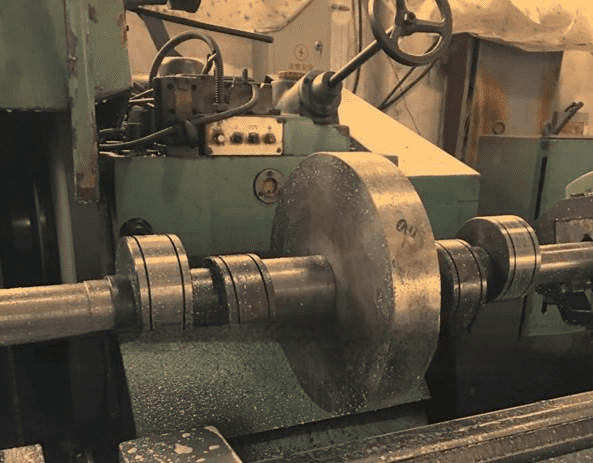
Because the pin path is generated by the CNC program, moving to a crankshaft with a different throw or pin layout becomes largely a programming and tooling task. Workholding, steady rests and wheel profiles still have to suit the new part, so the changeover is shorter but not free.
Where grinding sits in crankshaft production
Macerol's 2019 thesis notes that crankshafts are produced in three ways: cast, forged, or machined from billet. The majority of high-end crankshafts, including those for heavy-duty vehicles, are forged, machined, heat treated and then ground. Grinding is one of the last operations, so it carries much of the responsibility for meeting the geometrical and surface-integrity specification. A part that misses those requirements can be rejected, which reduces manufacturing capacity and adds cost and lost time.
The same thesis lists the design challenges that make crankshaft grinders special-purpose machines: the off-center pin journals, and the complex pin profile made up of a bearing surface, two sidewalls and the radius that connects them. Those features drive most of the strategy decisions described later.
How the X–C linkage keeps the wheel on the pin
Three quantities define the motion: the crank throw (the distance between the pin center and the main-journal center), the pin radius, and the grinding wheel radius. Wu et al. derive the X-axis position as a function of the crank angle from these three values, which gives the linkage model of the X axis and C axis.
Fang et al. write the same geometry as a contour control equation for the distance d between the wheel center and the crankshaft rotation center:
d(α) = R·cos α + √((r + R_gw)² − (R·sin α)²)
Here R is the eccentric distance of the pin (the crank throw), r is the pin radius, R_gw is the wheel radius and α is the crank angle. The CNC uses this relationship to drive the C axis and X axis together.
A worked example of the wheelhead stroke
Fang et al. ground production crankshafts with a pin journal diameter of 48.040 mm, an eccentric distance of 49.000 mm and a CBN wheel of 299.970 mm radius. Putting those values into the equation above:
| Crank angle α | Calculation | Wheel center distance d |
|---|---|---|
| 0° | 49.000 + 24.020 + 299.970 | 372.990 mm |
| 180° | −49.000 + 24.020 + 299.970 | 274.990 mm |
| Stroke | 372.990 − 274.990 | 98.000 mm |
The stroke equals twice the crank throw. In every revolution the wheelhead travels 98.000 mm out and back, and its velocity and acceleration change continuously with the crank angle. Wu et al. also specify a variable-speed C axis, so neither axis runs at constant speed. Any lag between the two axes shows up as a deviation in the pin contour, which is why control quality matters as much as static machine accuracy.
Machine architecture of a twin-wheelhead grinder
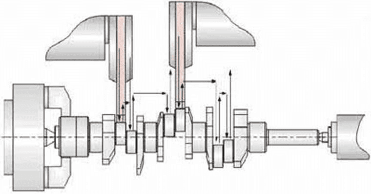
Wu et al. modelled a double grinding wheel crankshaft follow-up grinder. It is a special three-axis machine that completes the crankshaft through the linkage of two wheelhead feed axes, X1 and X2, with the workpiece rotary axis C.
In that machine the wheelhead feed axes are driven directly by linear servo motors and run on closed hydrostatic guides. The sliding platform of the wheelheads is driven by an AC servo ball screw, and the work spindle uses high-precision rolling bearings. The two branches can grind pin journals of different phases at the same time, or grind main journals and pin journals separately.
Grinding crankshaft journals: strategies for heat and wear
The pin profile is not a plain cylinder. It has a bearing surface, two sidewalls and a radius between them, and each region loads a different part of the wheel profile. The strategy used when grinding crankshaft journals therefore decides where heat is generated and where the wheel wears.
Macerol also points out that many crankpin grinding strategies have been patented by machine builders and embedded in the machines' NC software. That saves end users from developing their own process, but it can limit how freely they change the programs.
Main journals and multi-wheel plunge grinding
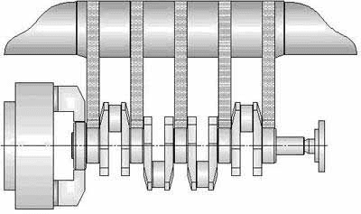
Main journals sit on the rotation axis, so they can be plunge ground like any cylindrical diameter. The diagram below shows one arrangement in which several wheels on one spindle plunge the main journals together. Because the wheel spacing is fixed to the journal spacing, such a wheel set suits a single crankshaft family, and a part with different spacing needs a different set.
Plunge versus angle plunge on the pins
Drazumeric et al. modelled plunge and angle plunge strategies and tracked how the fundamental grinding parameters change at each point of the pin profile. With radial plunge grinding, the specific material removal rate Q′ surges at the end of the cycle. That surge raises the likelihood of thermal damage, and the part of the wheel exposed to the most aggressive conditions wears excessively.
The angle plunge strategy reduces the variation in Q′, and the steadier load allows a shorter grinding cycle.
Sidewalls, radii and the dressing interval
On the sidewalls the likelihood of thermal damage is higher. Oliveira et al. compared two common sidewall strategies, axial plunge and axial face grinding, and proposed a multi-step approach in which several axial cycles are made at different radial positions.
When the wheel wear of the three strategies was modelled, axial plunge grinding gave the shortest dressing interval because of excessive wear on the radius. The multi-step axial strategy allowed the largest number of parts to be ground before redressing, because the number of steps can be changed to control where the wheel wears.
Temperature-based feed increments
Drazumeric, Krajnik and co-authors developed a strategy that uses Jaeger's moving heat-source model to identify the parts of the wheel that generate the most heat. Each feed increment is then set so that the critical points stay at or below a chosen maximum workpiece surface temperature.
Running the process on that burn threshold gave a significant reduction in cycle time compared with well-established strategies. For a production line, the practical message is that cycle time and surface integrity should be optimized together, with the burn limit as the boundary.
Why a CBN grinding wheel suits crankshaft following grinding
According to Macerol, a vitrified-bonded cBN wheel is the most commonly used tool in crankshaft grinding, particularly in finishing operations. In roughing, electroplated tools have proven very effective, reaching a specific material removal rate of up to 2000 mm³/mm·s. Superabrasive wheels replaced conventional wheels because of higher productivity and tool life, especially in large-volume production.
These wheels are normally built from a hub made of steel or carbon-fibre-reinforced plastic, carrying an abrasive layer about 3–5 mm thick that combines bond, grit and porosity. The vitrified bond must be strong enough to withstand the stresses of a high peripheral speed, yet fracture in a controlled way so the wheel stays sharp. Porosity gives the coolant room to flow and carries heat out of the grinding zone.
The abrasive itself is chosen for the workpiece material. Macerol notes that cBN is particularly successful in ferrous grinding because of its chemical inertness in that environment and its high thermal stability, while diamond is the better choice for ceramics and glass. Crankshafts are ferrous parts, so cBN is the natural fit. According to the same thesis, end users mostly grind with vitrified wheels that contain a high concentration of relatively strong cBN grains.
Low wear keeps the motion law valid
The X–C law contains the wheel radius. If the wheel shrank noticeably between dressings, the programmed path would drift away from the real contact point. Fang et al. state that when a superhard wheel such as CBN is chosen, the wheel radius may be treated as a constant because its wear is negligible.
That is a direct reason why CBN and following grinding work well together: the motion law stays valid for long runs between dressings. The same pairing is used for cam lobes, which are also non-circular in the machine's frame; see our overview of the camshaft machining process with CBN grinding.
Reading wheel speed on a specification sheet
Specification sheets usually give spindle speed in rpm and wheel diameter in mm. The peripheral speed follows from v = π·D·n / 60,000, with D in mm, n in rpm and v in m/s.
For example, the follow-up compound grinding machine series lists external grinding wheel diameters of 400 mm or 500 mm and a maximum cylindrical grinding head speed of 4,500 rpm. A 500 mm wheel at 4,500 rpm gives about 117.8 m/s, and a 400 mm wheel gives about 94.2 m/s. The usable speed is also limited by the maximum operating speed marked on the wheel itself, so check both values.
Accuracy, capability and inspection
Pin contour error as a process fingerprint
Fang et al. describe the contour error of the pin journal as the fingerprint of the pin chasing grinding process. Because the pin shape is generated by the C axis and X axis together, their position control errors are written into the contour.
In their experiment, a CNC with a trace function recorded the C-axis and X-axis position control errors with a sampling period of 4 ms. After grinding, a dedicated crankshaft measuring machine measured each pin contour with 1440 points per 360°, filtered with a Gaussian filter at a cutoff of 50 UPR. The contour error was then decomposed into components and mapped back to the axes.
The mapping held closely. Between the calculated and measured components, the difference was less than 0.1 µm on average for the components linked to the C axis, and less than 0.5 µm on average for those linked to the X axis. The authors propose using this mapping to predict the condition of the machine's key axes from routine contour inspection, which turns a quality record into a maintenance signal.
Machine geometric errors and compensation
Control errors are only part of the picture. Wu et al. list six position-dependent geometric errors for each motion axis, three linear and three angular, plus position-independent squareness errors between axes. For their twin-wheelhead machine, that adds up to 29 error terms.
They combined these terms into a precision machining model of the whole machine, based on multi-body system kinematics, as the foundation for error compensation in the NC code. When evaluating a machine, ask how its geometric errors are measured, which of them are compensated, and how often the compensation is checked.
Reading Cp and Cpk correctly
Capability indices are often quoted for crankshaft journals, and they are easy to misread. The NIST/SEMATECH e-Handbook defines Cp as the specification width divided by six standard deviations, Cp = (USL − LSL) / 6σ. Cpk is the smaller of (USL − µ) / 3σ and (µ − LSL) / 3σ, so it also accounts for how well the process is centered.
| Cp | Specification width | Share of the specification used by 6σ | Rejects (centered process) |
|---|---|---|---|
| 1.00 | 6σ | 100% | 0.27% |
| 1.33 | 8σ | 75% | 64 ppm |
| 1.66 | 10σ | 60% | 0.6 ppm |
| 2.00 | 12σ | 50% | 2 ppb |
The table shows a common mistake: a Cp of about 1.67 means the process spread uses about 60% of the tolerance, not 50%. Half the tolerance corresponds to Cp = 2.00. NIST also notes that the reject figures assume a normal distribution centered at the mean, which is why Cpk should be quoted next to Cp.
Choosing crankshaft grinding equipment
Choosing crankshaft grinding equipment starts with the part and the line, not with the catalog. The kinematics, wheel and inspection topics above translate into a short list of questions to settle before purchase.
Pre-purchase checklist
| Check | What to confirm | Why it matters |
|---|---|---|
| Part envelope | Crank throw, pin and main journal diameters, overall length, mass and number of throws | The X stroke equals twice the throw, and the envelope must fit the machine travel |
| Process route | Mains and pins in one clamping, number of wheelheads, roughing and finishing split | Sets cycle time, flexibility and the number of handling steps |
| X-axis drive | Drive type, guideways and the axis dynamics quoted for following motion | The wheelhead reverses twice per revolution under load |
| Wheel specification | Bond, abrasive, dressing method and expected dressing interval for your strategy | Wheel wear and dressing frequency drive cost per part |
| Peripheral speed | v = π·D·n / 60,000 against the wheel's marked maximum speed | Prevents overspeed and sets the attainable removal rate |
| Control and logging | Ability to trace C-axis and X-axis position errors | Enables the contour-to-axis diagnosis described above |
| Measurement | Contour measuring points, filter settings and gauge correlation | Contour figures are only comparable with the same method |
| Capability target | Characteristic, specification, Cp and Cpk definitions and sampling plan | Avoids comparing indices calculated in different ways |
| Changeover | Program, wheel, steady rest and workholding changes per part family | Determines how much of the flexibility gain is real |
UBright follow-up grinding machines
UBright supplies follow-up grinding machines for eccentric shafts and similar off-axis parts. The follow-up compound grinding machine combines turning and grinding with follow-up contour grinding. Its specification lists maximum machining diameters of ∅360 mm and ∅500 mm for the two larger configurations, machining lengths from 750 mm to 2,000 mm, a roughness of Ra 0.05 µm for internal and external cylindrical grinding, an axial positioning accuracy of 0.004 mm and an axial repeat positioning accuracy of 0.001 mm.
For larger parts, the vertical follow-up compound grinding machine uses a direct-drive torque rotary table, with worktable specifications from ∅400 mm to ∅1,600 mm. These values are catalog specifications, not results for a particular crankshaft. Automotive crankshaft lines need a part-specific review of envelope, cycle time and capability targets.
Our full range is listed under grinding machines, and the wider process chain is covered in our crankshaft manufacturing solutions.
Frequently asked questions
Is follow-up grinding the same as pin chasing grinding?
Yes. Follow-up grinding, pin chasing grinding, oscillating grinding and tangential point tracing grinding all describe the same principle: the crankshaft rotates about its main-journal axis while the wheelhead moves along X to stay tangent to each orbiting pin. Differences between machines lie in wheelhead layout, drives and control, not in the principle.
Can main and pin journals be ground in one clamping?
Yes. Main journals are ground like ordinary cylindrical diameters, and pins are ground by X–C interpolation, so both can be finished without relocating the part. Wu et al. describe a twin-wheelhead machine that can grind pins of different phases at the same time, or grind mains and pins separately.
Why is a CBN grinding wheel preferred for crankshafts?
Vitrified-bonded cBN is the most common choice for crankshaft finishing. cBN is chemically inert toward ferrous materials and thermally stable, and its negligible wear lets the control treat the wheel radius as constant. That keeps the programmed X–C path accurate between dressings.
What does Cp = 1.67 mean for a journal diameter?
It means the process spread of six standard deviations uses about 60% of the diameter tolerance. According to the NIST table, a centered process at Cp 1.66 produces about 0.6 ppm out-of-tolerance parts. Quote Cpk with it, because Cp alone ignores whether the process is centered.
Summary
- Crankshaft following grinding generates round pins by synchronizing the C axis with the wheelhead X axis, so the part stays in one clamping.
- The wheelhead stroke equals twice the crank throw, 98.000 mm in the published example, which makes X-axis dynamics and control critical.
- Plunge, angle plunge and multi-step strategies trade heat input, wheel wear and dressing interval; temperature-based feed increments can shorten the cycle at the burn limit.
- Vitrified-bonded CBN wheels dominate crankshaft finishing, and their low wear keeps the motion law valid.
- Pin contour error can be traced back to individual axes, and Cp or Cpk figures need their definitions to be meaningful.
Discuss your crankshaft grinding project
If you are planning a new crankshaft or eccentric-shaft grinding process, send us the drawing, annual volume, material and heat treatment, and the tolerance and capability targets. Our team can review the part against follow-up grinding machine options and the process route. Contact our grinding team to start the review.
References
- Modeling of Precision Machining for Crankshaft Follow-up Grinder — Wu C., Fan J., Zhang Y., Zhao Y., IOP Conference Series: Materials Science and Engineering 612 (2019) 032119, open access. Supports the X–C linkage principle, the twin-wheelhead machine architecture and the geometric error count.
- Development of Multi-grit cBN Grinding Wheel for Crankshaft Grinding — Macerol N., Licentiate thesis, Chalmers University of Technology, 2019. Supports crankshaft production routes, grinding strategies, dressing intervals and cBN wheel construction.
- Mapping Relation between Contour Error Components of Crankshaft Pin Journal and Axis Position Control Error of Oscillating Grinding Machine — Fang X., Sheng X., Sun Y., Xu Y., Sensors 2021, open access. Supports the comparison with fixture-based grinding, the wheel-center equation, the experimental values and the contour error mapping.
- What is Process Capability? — NIST/SEMATECH e-Handbook of Statistical Methods, section 6.1.6. Supports the Cp and Cpk definitions and the capability-to-rejects table.