
Power skiving is a continuous gear-cutting process that combines the rotating-tool motion of hobbing with the generating action of shaping. A cutter and a workpiece rotate simultaneously about their own axes while the cutter’s axis is set at an angle to the workpiece axis. That angled relationship, together with an axial feed, is what removes material along the full tooth length in one continuous pass.
Power skiving gear cutting fundamentals
Power skiving gear cutting depends on getting three things right at once: the axis cross angle, the synchronized rotation ratio between tool and workpiece, and a cutter geometry that matches the target tooth form. The sections below walk through how those pieces fit together, where the process is strong, and where it still hits a wall.
Key takeaways
- Power skiving generates teeth through a crossed-axis, continuously rotating motion, not through a reciprocating stroke like shaping or a linear pull like broaching.
- The axis cross angle and the resulting tilt angle are the two parameters that actually define the cut; they are not optional tuning knobs.
- The process reaches internal and external gears with equal cutting principles, but very large modules, very large diameters, or tight tool-to-part clearance can rule it out.
- Cutter design and coating selection change the achievable cutting speed and tool life, but they do not change the underlying kinematics.
Table of Contents
- Power skiving gear cutting fundamentals
- What makes power skiving a distinct process
- The axis cross angle and how the cutting motion is built
- Cutter geometry: why the tool looks like a shaper cutter
- Internal gears versus external gears: where the process fits
- Where power skiving reaches a hard limit
- How power skiving compares with shaping, hobbing, and broaching
- Planning questions before specifying a power skiving process
- What a power skiving process specification should document
- Frequently asked questions
- Conclusion
- References
What makes power skiving a distinct process
Conventional gear-shaping cuts teeth with a reciprocating shaper cutter that strokes back and forth while indexing around the workpiece. Broaching pulls a long, stepped tool through a bore in a single linear motion. Power skiving does neither. The cutter and the workpiece both rotate continuously, and the cutting action comes from the relative sliding motion created by the angle between their two rotation axes.
Because both members are always turning, there is no idle return stroke the way there is in shaping. Every degree of rotation on the cutter is doing cutting work somewhere around the part. That is the structural reason the process can run faster than shaping at a comparable finish quality, and it is also why the process places different demands on the machine: spindle synchronization and axis-angle control matter more than raw stroke force.
The axis cross angle and how the cutting motion is built
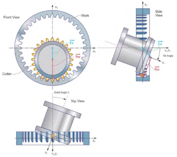
The defining geometric parameter in power skiving is the axis cross angle, usually written as the shaft angle Σ. The cutter’s rotational axis is tilted relative to the workpiece’s rotational axis by this angle. With the cross angle set, the cutter is fed axially along the workpiece while both parts rotate at a synchronized ratio tied to their tooth counts.
The combined motion — cutter rotation, workpiece rotation, and axial feed, all happening at once — produces a generating action: the cutter’s teeth sweep through positions that correspond to successive points on the involute tooth profile, in the same way a rack or a shaper cutter generates a profile by rolling contact. The practical difference is that skiving does this continuously and along the workpiece’s axial length in a single pass, rather than through discrete strokes.
The tilt angle is a secondary but necessary parameter. Because the cutter axis is not parallel to the workpiece axis, the tool’s effective rake and clearance angles at the cutting edge change as a function of the cross angle. Cutter design has to account for this from the start; it cannot be treated as a fixed shaper-cutter geometry simply re-angled in the machine.
A useful way to state the principle for planning purposes: the axis cross angle and the tilt angle are not adjustment variables to fine-tune after the fact — they are the definition of the cut. Get them wrong, and the resulting tooth form is wrong regardless of feed rate, coating, or spindle speed.
Cutter geometry: why the tool looks like a shaper cutter
The power skiving cutter’s basic shape resembles a shaper cutter because both tools have to generate an involute profile through a rolling relationship with the workpiece. When the workpiece has straight (spur) teeth, the cutter is typically helical; when the workpiece has helical teeth, the cutter is typically straight. In both cases, when the target tooth form is an involute, the theoretical cutting edge — whether the cutter itself is straight-toothed or helical-toothed — traces an involute profile in the relevant cross-section.
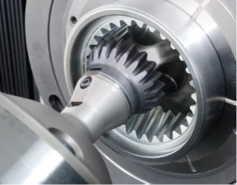
The theoretical cutting edge of the tool is derived from the contact line that develops between the tool tooth surface and the workpiece tooth surface during the generating motion. This is why cutter regrinding and resharpening in power skiving follow the same logic used for shaper cutters: the relief is ground on the face, following the geometry that keeps the contact-line relationship correct as the edge wears back.
Tool material and coating selection affect the achievable cutting speed range, not the underlying geometry. Carbide-based cutters with wear-resistant coatings are commonly matched to specific cutting-speed regimes for wet or dry operation, and the coating choice is a tool-engineering decision made against the target material, cutting speed, and expected tool life — not a substitute for correct cutter geometry.
Internal gears versus external gears: where the process fits
Power skiving cuts both internal and external cylindrical gears using the same underlying kinematic principle: crossed-axis rotation plus axial feed. What changes between the two cases is the relative geometry of cutter and workpiece, not the generating mechanism itself.
Internal gear machining with power skiving
Internal gear machining is one of the areas where power skiving is most frequently evaluated against the alternatives, because the geometry of an internal tooth form creates a specific access problem that the other processes solve in different ways. Broaching solves it with a dedicated, part-specific tool that is pulled through the bore in a single linear pass — fast, but inflexible to any change in tooth form. Shaping solves it with a reciprocating cutter that strokes in and out of the bore, which works reliably but needs enough axial clearance inside the bore for the full stroke plus tool retraction.
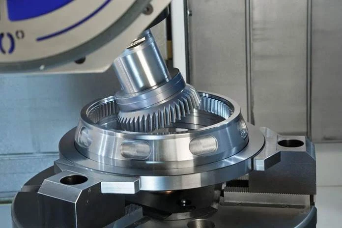
Power skiving’s crossed-axis, continuously rotating cutter does not need that reciprocating stroke clearance. Because the tool’s axis is angled rather than parallel to the bore axis, and both cutter and workpiece are turning the whole time, the cutter can approach an internal tooth form and cut along its full length without requiring room for a return stroke behind it. That is the specific access advantage that internal gear machining with power skiving is evaluated for, and it is a geometric property of the crossed-axis motion, not a claim about speed or accuracy in isolation.
The comparison is still case-by-case. A bore that is short relative to its diameter, or a part that already has generous clearance behind the tooth form, may not need that advantage at all — shaping or broaching may remain perfectly workable, and each brings its own strengths (broaching’s raw cycle speed for a fixed, unchanging profile; shaping’s tolerance for large modules and complex interference geometry). The internal-access advantage becomes decisive specifically when the bore geometry, an adjacent shoulder, or a nearby feature leaves too little room for a reciprocating stroke or a long broach body.
External gear cutting
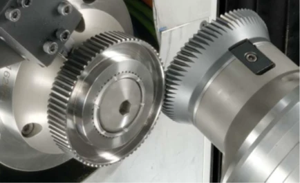
For external gears, the same crossed-axis approach applies without the internal-access advantage being the deciding factor, because a reciprocating shaper cutter or a rotating hob generally has enough clearance to reach an external tooth form without the same bore-geometry constraint. Here the comparison against hobbing and shaping is driven more by cycle time, achievable accuracy grade on the specific part, and whether a feature sits close enough to an interfering shoulder or flange that a hob’s full-length engagement becomes a problem.
An external gear near a flange or a shoulder can face a version of the same interference issue that shows up on internal gears: the cutting tool needs a clear approach and retract path, and a feature that partially blocks that path narrows the list of processes that can reach it cleanly. Evaluating power skiving for an external tooth form close to an interfering feature follows the same logic used for internal gears — check the actual clearance the cutter needs against the actual part geometry, rather than deciding by tooth-form type alone.
Where power skiving reaches a hard limit
Power skiving does not replace shaping or hobbing outright. The process reaches a practical limit under a few specific conditions:
- Large module or large diameter gears. Above a certain module and workpiece diameter, the combination of required cutter size, achievable cutting forces, and machine rigidity makes power skiving impractical, and shaping remains the more reliable choice.
- Tool-to-part interference. When the cutter’s crossed-axis geometry cannot clear an adjacent shoulder, flange, or feature on the workpiece, shaping’s straight-in stroke may be the only motion that fits.
- Very tight tolerance combined with an unproven setup. As with any generating process, the achievable accuracy grade depends on machine synchronization accuracy, cutter condition, and workholding rigidity being demonstrated on the actual part — not assumed from a general capability claim.
These are the same categories of constraint that apply to any gear-generating process: geometry access, machine capability, and tolerance requirements have to be checked against the specific part before the process is specified, not after.
Why module and diameter set a ceiling
The module-and-diameter limit is not an arbitrary cutoff; it follows from how the crossed-axis motion loads the cutter and the machine. As module increases, the cutter has to remove more material per tooth pass, and the tilted axis relationship means that cutting force is distributed differently along the tool than it would be in a straight-axis process like hobbing. A larger workpiece diameter also increases the torque the spindle drive has to deliver while maintaining the precise rotational synchronization the generating motion depends on.
Machine builders publish a working envelope for a given power skiving machine platform — a maximum module and diameter combination the machine is rated for — and that envelope is a property of the specific machine’s spindle power, synchronization control, and structural rigidity, not a universal number for the process as a whole. A planner evaluating a large gear should treat the published envelope for the candidate machine as the relevant constraint, rather than assuming any power skiving-capable machine can reach any module.
Interference geometry in practice
Tool-to-part interference is easiest to picture as a clearance problem: the cutter, its holder, and the machine’s tool-change or retract path all need room to move through the crossed-axis motion without touching a feature the process is not supposed to cut. A shoulder immediately adjacent to the tooth form, a flange that partially obstructs the cutter’s approach angle, or a feature on the opposite face of a thin part can all narrow or eliminate that clearance.
This is a case where a CAM simulation using the actual cutter geometry, holder, and machine kinematics is more reliable than a hand calculation, because the crossed-axis motion sweeps through positions that are not always intuitive from a 2D drawing. The same discipline that applies to workholding-and-tool-access planning on other multi-axis processes applies here: simulate with the real fixture and holder, not a nominal part-only model.
How power skiving compares with shaping, hobbing, and broaching
The table below summarizes the structural differences in cutting motion. It intentionally does not include specific productivity multipliers, DIN accuracy grades, or surface-roughness values, because those figures are process-, machine-, and part-specific and should be established on the actual production setup rather than carried over from a general comparison.
| Process | Cutting motion | Typical strength | Typical limitation |
|---|---|---|---|
| Power skiving | Continuous crossed-axis rotation with axial feed | No idle return stroke; can reach some internal-gear geometries without stroke clearance | Large module/diameter and severe interference conditions push the process toward its limit |
| Gear shaping | Reciprocating stroke with rotary indexing | Reliable at large module and diameter; tolerant of interference geometry | Reciprocating stroke and indexing add non-cutting time |
| Gear hobbing | Continuous single-axis generating roll | Well established for external gears; flexible tooth count and helix range | Not suited to internal gears; access-limited near interfering shoulders |
| Broaching | Single-pass linear pull with a stepped, part-specific tool | Very fast cycle for the specific profile it is built for | Tool is dedicated to one profile; inflexible to design change |
Reading this table as “skiving beats X on every dimension” would misstate the comparison. Each process trades stroke or motion complexity for a different set of access and flexibility characteristics, and the right choice depends on the part’s geometry, tolerance, and production volume.
Planning questions before specifying a power skiving process
- Does the tooth form sit close enough to a shoulder, bore step, or flange that shaping’s stroke clearance becomes the limiting factor instead of the cutting motion itself?
- Is the target module and gear diameter within the range that has been demonstrated on the intended machine, cutter, and workholding combination?
- Is the tooth accuracy requirement tied to a machine-and-tooling capability that has been proven on the actual part, or only assumed from a general process description?
- Does the cutter geometry — helical or straight, coating, and material — match both the target tooth form and the intended cutting environment (wet or dry)?
- Has the axis cross angle and tilt angle been verified for the specific gear ratio and helix angle involved, rather than copied from an unrelated part program?
What a power skiving process specification should document
A process specification for a new part should make the following explicit rather than implicit, so that anyone reviewing the program later can see how the cut was actually derived:
- The axis cross angle and the resulting tilt angle, tied to the specific gear ratio and helix angle of the part in question — not copied from a similar-looking prior job.
- The cutter’s tooth form and material/coating combination, matched to the target tooth form (straight or helical) and the intended cutting environment (wet or dry).
- The module and diameter range the machine platform is rated for, checked against the actual part rather than assumed from the process name alone.
- A tool-access simulation using the real fixture, holder, and cutter geometry, covering every position the cutter passes through during the crossed-axis motion — not a nominal part-only check.
- The verification method and accuracy grade being targeted, established on the actual machine, cutter, and workholding combination for this part, not inferred from a general capability claim about the process.
Documenting these five items does not guarantee a successful setup on its own, but it does make the underlying assumptions visible, which is what allows a team to diagnose a problem quickly if the first parts off the process do not meet the target tooth form or tolerance.
Frequently asked questions
Is power skiving faster than gear shaping?
The continuous, crossed-axis motion in power skiving removes the idle return stroke that gear shaping requires, which is the structural reason the process can cut faster at a comparable accuracy grade. The actual cycle-time difference on a given part depends on the module, tooth count, and machine, so it should be measured on the intended part rather than assumed from a general figure.
Can power skiving cut internal gears?
Yes. Power skiving cuts internal and external cylindrical gears using the same crossed-axis, continuously rotating principle. Internal gearing is one of the areas where the process is most often evaluated against shaping and broaching, because the rotating cutter can approach the internal tooth form without needing the stroke clearance a reciprocating tool requires.
Does power skiving replace gear shaping entirely?
No. Very large module or large diameter gears, and geometries where the cutter cannot clear an interfering feature, still favor shaping. Power skiving is best treated as an additional process option to evaluate against the part’s specific geometry and tolerance requirement, not a universal replacement.
What determines the cutter shape in power skiving?
The cutter’s theoretical cutting edge is derived from the contact line that develops between the tool and the workpiece tooth surfaces during the crossed-axis generating motion. Whether the cutter ends up straight-toothed or helical-toothed depends on the workpiece’s own tooth form, and the coating and material are selected against the target cutting speed and wet-or-dry cutting environment.
Conclusion
Power skiving generates gear teeth through a continuous, crossed-axis rotating motion rather than a reciprocating or pulling stroke. The axis cross angle and tilt angle define the cut, the cutter geometry has to be derived from the same generating relationship that produces the tooth form, and the process reaches both internal and external gears through the same underlying principle — with large module, large diameter, and severe interference geometry marking where the process meets its practical limit.
If you are evaluating gear-cutting process options for a specific part geometry, tolerance class, and production volume, contact UBright Solutions to discuss which combination of machine, workholding, and process planning fits your application.
References
- EMAG — Power hobbing vs. power skiving — supports the crossed-axis rotational relationship between cutter and workpiece and the comparison against hobbing.
- EMAG — Power Skiving of gears: alternative to broaching and gear shaping — supports the internal-gear access comparison against broaching and shaping.
- Gear Solutions — Power skiving: High quality, productivity, and cost efficiency in gear cutting — supports the axis cross angle definition and the continuous cutting motion description.