
API pipe thread machining is the process of cutting standardized threaded connections onto oil-country tubular goods (OCTG) — the casing and tubing that line and produce oil and gas wells. The thread is the joint that holds a well together, so its accuracy decides whether a string seals under pressure thousands of meters downhole. This article walks through a purpose-built machine designed specifically for large-diameter API pipe thread machining, covering its layout, an electromagnetic expanding fixture for thin-wall pipe, servo and spindle selection, finite-element validation, and the accuracy and efficiency it achieved in testing.
Table of Contents
- What is API pipe thread machining?
- Why large-diameter API pipe threads are hard to machine
- Purpose-built machine design
- Electromagnetic expanding fixture for thin-wall clamping
- Support-system stiffness
- Servo system: linear-motor feed and electric spindle
- Thread-turning process and cutting parameters
- Measured results: accuracy, efficiency, reliability
- FAQ
- Conclusion
What is API pipe thread machining?
API pipe thread machining produces tapered, standardized threads on pipe ends and couplings so they connect reliably and seal under load. The dimensions and tolerances follow specifications published by the American Petroleum Institute (API), such as API 5B and API 5CT, which define thread form, taper, pitch, and gauging for casing and tubing connections. Because these joints are the weakest mechanical link in a well string, the machining process has to repeat the same thread profile part after part within tight limits.
In practice, the work centers on a few demands at once: holding the pitch and tooth-form geometry the standard requires, finishing the thread flanks smoothly enough to seal, and doing it on pipe that is large in diameter but thin in wall. Those competing demands are what make a general-purpose lathe a poor fit and a dedicated machine worthwhile.
Why large-diameter API pipe threads are hard to machine
Large-diameter OCTG — in this project, sizes from 10¾” to 13⅜” — combines a big swing with a relatively thin wall. That geometry creates two problems that smaller, solid parts never face.
Thin-wall distortion
A traditional three-jaw chuck grips at three points. On a thin-wall pipe, those points concentrate stress and pull the cross-section slightly out of round before a single tooth is cut. Any distortion during clamping shows up directly in the finished thread, so the connection no longer gauges correctly. Controlling clamping deformation is therefore the central challenge in large diameter pipe thread machining, not an afterthought.
Accuracy and connection integrity
API casing and tubing threads are tapered, so pitch and tooth-form errors accumulate along the engagement length. The machine has to coordinate spindle rotation and tool feed precisely enough to hold the pitch (5.08 mm in this case) and the tooth height (1.575 mm) across the full thread. Surface finish matters too: rough flanks leak. A machine built for OCTG thread machining has to deliver both the geometry and the finish in one repeatable cycle.
Purpose-built machine design
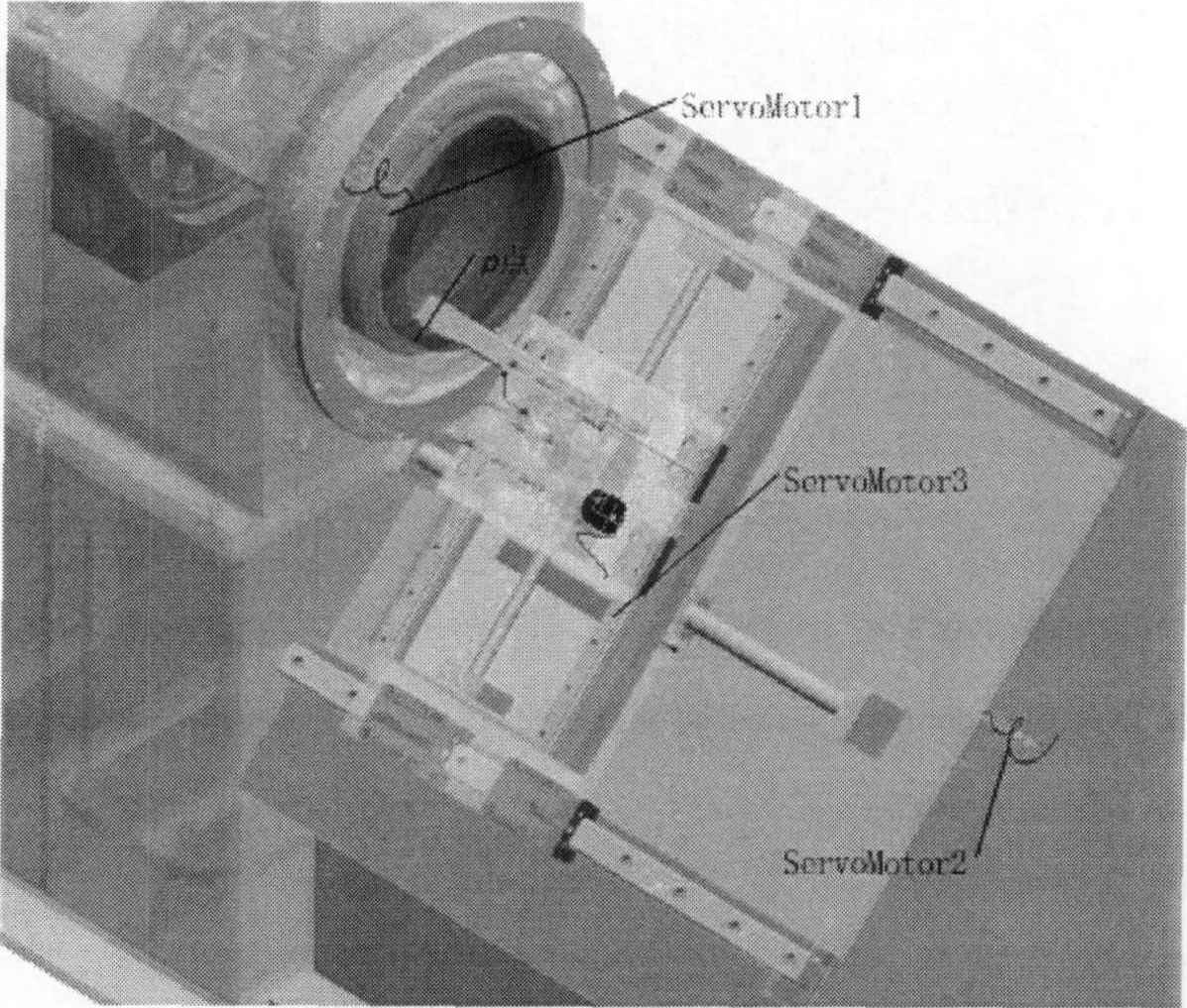
The machine targets a clear envelope: a maximum machining diameter of 400 mm, machining length up to 300 mm, spindle speed of 400–800 rpm, X-axis travel of 177 mm, and Z-axis travel of 575 mm. It weighs about 13,000 kg with a footprint of 4,000 × 2,000 × 1,917 mm. Everything below serves three goals the design fixed up front: high precision, high efficiency, and high reliability.
45° slant-bed layout
The bed uses a 45° slant rather than a flat-rail layout, for three practical reasons. Chips fall straight into the conveyor at the base instead of piling up and feeding heat back into the work. The slant lets the structure carry vertical and horizontal cutting forces at the same time, which steadies the cut. And it keeps tooling and fixtures within easy reach for tool changes and setup. A separated, rather than one-piece, bed design further tunes the stiffness distribution.
Motion scheme: workpiece rotates, tool feeds
Four motion arrangements were compared. The chosen scheme assigns the rotating primary motion to the workpiece and the axial and radial feed to the tool carriage. This lowers control complexity, and because the carriage is lighter than the combined workpiece-and-fixture mass, it cuts drive energy and shrinks the machine footprint while improving accuracy.
flowchart LR
    A[Overall design] --> B[Motion simulation and interference check] --> C[Manufacture and assembly] --> D[API pipe thread machining]
Motion simulation and interference check
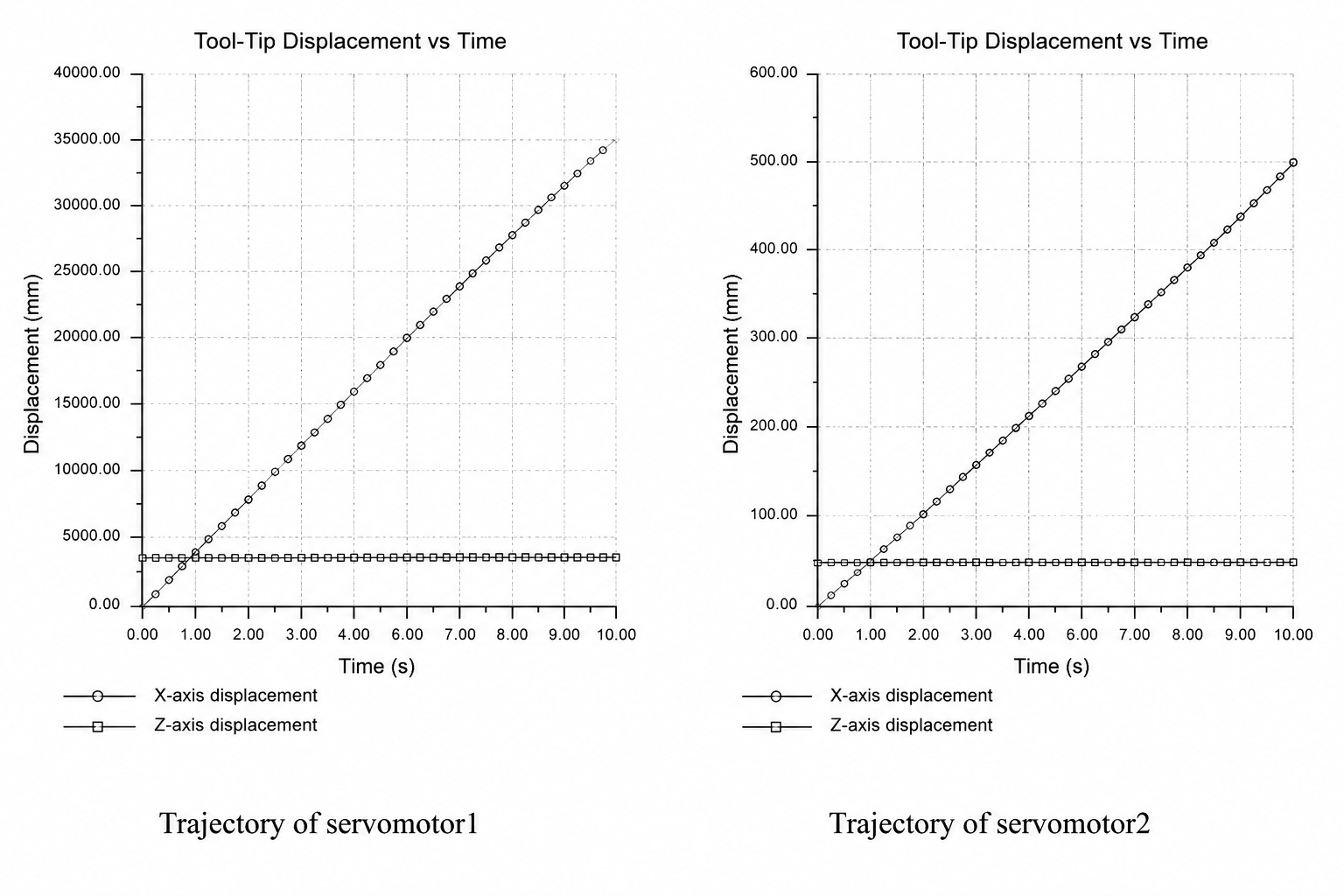
After 3D modeling and virtual assembly, the design was checked two ways. A global clearance and interference analysis confirmed the parts assemble without collision. Then a kinematic simulation drove the model with the planned servo parameters — primary motor at 3,600 deg/s, axial feed at 50.8 mm/s, radial feed at 3.175 mm/s — to trace the tool path. The simulated tool-tip displacement-versus-time curve matched the design intent, and the coordinated X/Z motion satisfied the API thread form, confirming the concept before any metal was cut.
Electromagnetic expanding fixture for thin-wall clamping
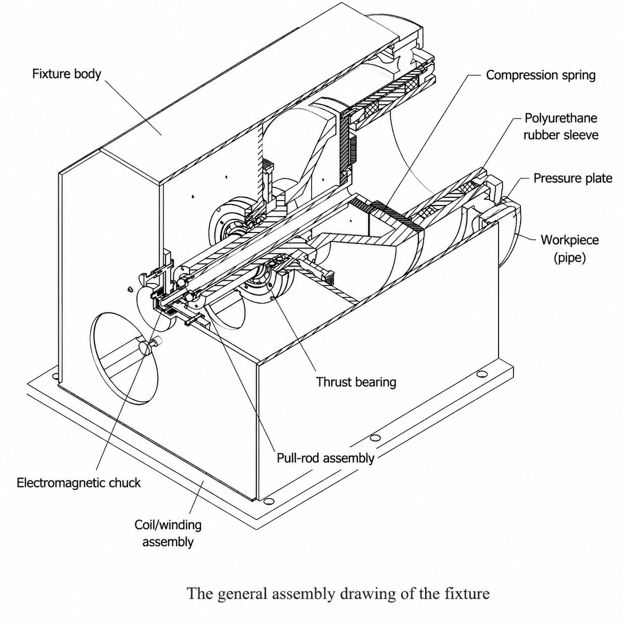
The fixture is the part of the machine that solves the thin-wall distortion problem directly. Instead of a three-jaw chuck, it uses an “electromagnetic drive plus elastic expansion” design built around an electromagnetic chuck, a winding assembly, a pull-rod assembly, the fixture body, and a polyurethane rubber sleeve.
An electromagnetic chuck (24 V DC, up to about 200 kgf of holding force) supplies the actuating force — compact, fast-responding, and easier to control precisely than hydraulic or pneumatic drives. A winding assembly with a thrust bearing decouples the chuck from the rotating parts so the workpiece can spin without tangling the supply lines, and a compression spring releases the part quickly when power is cut. The clamping element itself is a polyurethane rubber sleeve, chosen for its high elasticity and even deformation: it grips the thin wall uniformly around the full circumference rather than at three stress points.
Clamp and release working cycle
flowchart LR
    A[Chuck energized] --> B[Force through winding and pull-rod] --> C[Polyurethane sleeve expands radially] --> D[Static friction clamps pipe]
    D --> E[Machining]
    E --> F[Chuck de-energized] --> G[Spring resets, sleeve rebounds] --> H[Pipe released]
FEA of clamping force versus distortion
A nonlinear large-deformation contact analysis validated the grip. Modeling the polyurethane sleeve with a Mooney-Rivlin hyperelastic material and applying 50 kPa of clamping pressure, the contact pressure reached 0.407 MPa and the resulting static friction was 10,274.1 N — well above the 3,785.94 N cutting force the thread operation needs, so the pipe stays firmly held. The key result for thin-wall work: maximum workpiece distortion was only 0.38 mm, within the limit the API thread standard allows. The fixture grips hard enough to cut but gently enough to keep the pipe round.
Support-system stiffness
Accuracy also depends on the large structural parts staying still under load. Two were validated by finite-element analysis.
The fixture box is a welded structure with 16 mm plate and an internal stiffener. Modal analysis put its first natural frequency at 180 Hz — against a working excitation base frequency of roughly 6.67–13.3 Hz, that is about a 10× safety margin, so the machine does not resonate during cutting. The full set of first-ten modes ran from 180 Hz to 447 Hz.
The machine bed is a welded closed box section with a minimum 16 mm wall, square-and-V combined ribbing, and a post-weld anneal to relieve internal stress. Under a 400 kPa rail-load case simulating the cut, static analysis showed maximum deformation of 4.9 × 10⁻⁴ mm in Y and 1.15 × 10⁻³ mm in Z — both within the allowable limits, confirming the bed stiffness is adequate for the work.
Servo system: linear-motor feed and electric spindle
The drive train pairs linear-motor feed with an electric spindle to hit the precision and response that API thread cutting needs.
Linear-motor feed
The X and Z axes use linear motors rather than the usual rotary-motor-plus-ballscrew chain. Removing that intermediate transmission takes the drive-chain length to zero, which removes backlash and lost motion. The result is roughly 12 µm repeatability and 250 nm absolute positioning. The axes also respond fast — the X-axis motor delivers about 286 N peak thrust at up to 201 m/s², and the Z-axis motor about 1,090 N at up to 263 m/s² — and travel can be extended by joining secondary tracks to suit different machining lengths. Matched servo drives (continuous current 6 A on X and 20 A on Z, 100–247 VAC input) keep the system aligned with the motors.
Electric spindle
The spindle is sized from the cut. Using the thread-cutting force formula with the project parameters (pitch 5.08 mm among them) gives a cutting force of 3,785.94 N and a cutting power of about 11.6 kW. The machine uses an electric spindle rated 12 kW (18 kW peak) running 2,000–4,000 rpm, geared 1:5 to land the 400–800 rpm working range. A built-in encoder feeds speed back in real time so spindle rotation and feed stay synchronized — the condition for holding pitch accuracy in any pipe thread turning operation.
Thread-turning process and cutting parameters
The threads are cut by turning, using form tools on a combined tool holder so the machine finishes the external thread and then switches directly to the internal thread without re-clamping — fewer setups, less idle time. The working parameters are a 750 rpm spindle speed, 50.8 mm/s axial feed, and 3.175 mm/s radial feed, with high-pressure emulsion coolant that both cools the tool and breaks chips. Keeping the part clamped across both thread operations is what protects the alignment between external and internal threads.
Measured results: accuracy, efficiency, reliability
The machine was tested on both 10¾” and 13⅜” API pipe threads, and the results held to API requirements:
– *Accuracy: pitch accuracy reached grade 8, tooth-form error stayed at or below 0.02 mm, and surface roughness came in at Ra 0.63–1.25 µm. – Efficiency: per-part machining time dropped about 30% versus the prior general-purpose setup, and auxiliary time (clamping and tool changes) fell about 40%, supporting continuous automated production. – Reliability:* 72 hours of continuous running with no fault, clamp repeatability at or below 0.01 mm, and bed thermal deformation at or below 0.03 mm — enough for high-volume production.
As a project outcome, building the machine around localized core components (the fixture and servo system) reached roughly 80% component localization and brought equipment cost more than 50% below a comparable imported machine. These are UBright project results from this build, not figures drawn from an external study.
FAQ
What is API pipe thread machining?
It is the machining of tapered, standardized threads — defined by API specifications such as API 5B and API 5CT — onto OCTG casing and tubing so the joints connect and seal reliably downhole. The thread form, pitch, taper, and gauging all follow the standard.
How are large-diameter API pipe threads machined without distorting thin walls?
The decision rule is to clamp by uniform elastic pressure rather than point contact. An electromagnetic expanding fixture pushes a polyurethane sleeve out evenly around the full circumference, so the holding friction exceeds the cutting force while keeping workpiece distortion small — in this machine, 0.38 mm — instead of pulling a thin pipe out of round the way a three-jaw chuck can.
What accuracy can API pipe thread machining achieve?
On this machine, testing on 10¾” and 13⅜” threads reached grade-8 pitch accuracy, tooth-form error at or below 0.02 mm, and Ra 0.63–1.25 µm surface finish — within API requirements. Actual results depend on pipe size, material, and tooling condition.
Why use a 45° slant-bed machine for pipe thread machining?
The slant lets chips fall away from the work into the conveyor instead of trapping heat, balances vertical and horizontal cutting forces for a steadier cut, and keeps tooling reachable for fast setup. Those are practical gains a flat-rail bed does not give on heavy pipe work.
What pipe sizes can this machine handle?
It was built and tested for large-diameter OCTG from 10¾” to 13⅜”, with a maximum machining diameter of 400 mm and machining length up to 300 mm.
Conclusion
Large-diameter API pipe thread machining comes down to holding a standardized thread on pipe that wants to distort. This purpose-built machine answers that with a coordinated design: a 45° slant bed for stability and chip control, an electromagnetic expanding fixture that clamps thin walls uniformly, linear-motor feed and an electric spindle for precise synchronized motion, and FEA validation behind each major part — together delivering grade-8 pitch accuracy and a 72-hour fault-free run in testing.
If you are planning OCTG thread machining or evaluating equipment for large-diameter API pipe threads, UBright can help. Share your pipe sizes, thread specs, and drawings, and our team will work through the machining requirements and an equipment plan with you.
References
- American Petroleum Institute — Source of the API 5B and API 5CT specifications governing OCTG casing and tubing thread dimensions, tolerances, and gauging referenced throughout this article.